background image

©


CIAS Elettronica S.r.l. 


Ed. 1.2 

Manuale di Installazione


Pagina 

21 

di 

48


MICRO-RAY 


TIPO DI APPLICAZIONE 

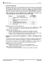
È  possibile  scegliere,  tra  i  5  tipi  di  applicazione,  quello  più  opportuno  che  potrà  essere 
differente per ogni raggio considerato. Quello riferito al raggio 1, sarà dedicato soprattutto 
allo strisciamento, quello dei raggi 2 e 3 alla corsa, il raggio 4 (se presente) riferito allo 
scavalcamento. Posizionando il commutatore di funzione 

SW1 in posizione 3

, è possibile 

leggere e/o impostare, al raggio sul quale si sta agendo, i tipi di applicazione disponibili. 

Tutti  i  raggi  possono  essere  impostati  con  le  5  applicazioni.  Di  seguito  viene 
consigliata quella più consona rispetto alla posizione del raggio. 


Numero 

Tipo di applicazione 

Consigliata 

per il Raggio  

Antistisciamento / Antiscavalcamento 
Basic 

Antistisciamento / Antiscavalcamento 
Advanced 

Corridoi delimitati da un solo lato 

2; 3; 4 

Corridoi delimitati da entrambi i lati 

2; 3; 4 

Spazi aperti 

2; 3; 4 


  Modifica

 (selezione) del tipo di applicazione: 

  Selezionare un numero da 00 a 04 sugli appositi commutatori 

SW2

 (decine) e 

SW3


  Premere il pulsante 

S3

per confermarne l’acquisizione e la messa in uso 

Lettura

 del tipo di applicazione; 

  Ruotare il commutatore SW2 fino a quando il led rosso (D9) si accende 

  Ruotare il commutatore SW3 fino a quando il led rosso (D8) si accende 

Il numero da 00 a 04 rappresentato sui commutatori SW2 (decine) e SW3 (unità), 
corrisponde al tipo di applicazione attualmente assegnato al raggio 


TIPOLOGIE  DI  FILTRO  DISTURBI  AMBIENTALI  E  TEMPO  DI  INTERRUZIONE  DEI 
RAGGI 

In questa fase 

si può procedere con l’impostazione del filtro per disturbi ambientali e tempi 

di interruzione dei raggi, 

analizzando l’ambiente in cui abbiamo installato MICRO-RAY.  

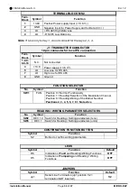
Posizionando  il  commutatore  di  funzione 

SW1  in  posizione  5,

  è  possibile  leggere  e/o 

impostare il filtro per disturbi ambientali ed il tempo di interruzione dei raggi. 

Modifica

 del filtro per disturbi ambientali: 

  Selezionare un numero da 0 a 1 sul commutatore 

SW2

 (decine).  

  Premere il pulsante 

S3

, per confermarne 

l’acquisizione e la messa in uso 

Lettura

 del filtro per disturbi ambientali: 

  Ruotare il commutatore SW2 fino a quando il led rosso (D9) si accende 


Содержание MICRO-RAY

Страница 1: ...20MACIE0402 MICRO RAY Barriera con raggi a microonda Manuale di Installazione Multi Rays Microwave Barrier Installation Manual Edizione Edition 1 2...

Страница 2: ...ITO TX 9 MORSETTIERE CONNETTORI E FUNZIONALIT DEL CIRCUITO RX 11 MORSETTIERE DEL CIRCUITO INTERFACCIA MICRO RAY 13 ALIMENTAZIONE 14 Alimentazione 13 8 V 14 Alimentazione con kit opzionali IP DOORWAY 1...

Страница 3: ...T 32 TERMINAL BLOCKS CONNECTORS AND FUNCTIONALITY OF THE RX CIRCUIT 34 TERMINAL BLOCKS OF THE MICRO RAY INTERFACE CIRCUIT 36 POWER SUPPLY 37 Power supply 13 8 V 37 Power supply with optional IP DOORWA...

Страница 4: ...barriera in grado di rilevare l interruzione dei raggi compresi tra la colonna A e la colonna B causata dalla presenza di un corpo che si muove all interno del campo sensibile I segnali ricevuti dai s...

Страница 5: ...A questo punto inserire l apposita spina nella colonna solo dopo aver posizionato la staffa a L di bloccaggio Fig 3 Fatto questo si pu proseguire con il fissaggio delle viti in dotazione Fig 4 Nella p...

Страница 6: ...dicato nella tabella sottostante in caso di manutenzione sostituzione di un raggio o parte di esso bisogner consultare obbligatoriamente la tabella L errato posizionamento comporta malfunzionamenti de...

Страница 7: ...CIAS Elettronica S r l Ed 1 2 Manuale di Installazione Pagina 6 di 48 MICRO RAY Colonna A Colonna B Figura 7 2 3 1 4 3 2 1 R4 A RX R3 A RX R2 A TX R1 A TX R4 B TX R3 B TX R2 B RX R1 B RX 4...

Страница 8: ...stallata molto vicina alle recinzioni metalliche la recinzione stessa deve essere accuratamente fissata in modo che il vento non ne provochi grande movimento Gli alberi le siepi i cespugli la vegetazi...

Страница 9: ...i rete o muratura la barriera posta ad una distanza che va dai 90cm ai 160cm dal muro recinzione potrebbe essere soggetta a fenomeni che rendono difficoltoso l allineamento del dei raggio i centrali I...

Страница 10: ...X Figura 11 Disposizione topografica dei componenti nel circuito MORSETTIERA MS1 Mors Simbolo Funzione 1 TMP Contatto Rel di Manomissione C Nota 1 2 TMP Contatto Rel di Manomissione NC Nota 1 3 FLT Co...

Страница 11: ...ELLE FUNZIONI N Simbolo Funzione SW1 FUN Posizione 0 Normale funzionalit Posizione 1 Lettura Selezione del Canale di Modulazione Posizione 8 Lettura Scrittura del Numero di Tratta Posizioni 2 3 4 5 6...

Страница 12: ...e NC 3 TMP Contatto Rel di Manomissione C Nota 1 4 TMP Contatto Rel di Manomissione NC Nota 1 5 FLT Contatto Rel di Guasto C 6 FLT Contatto Rel di Guasto NC 7 STBY Ingresso Tamper Colonna Norm Chiuso...

Страница 13: ...di Manomissione OFF D10 Indicazione di Guasto OFF D9 Funzioni Allineamento e Regolazione OFF D8 Funzioni Allineamento e Regolazione OFF PULSANTE Simbolo Funzione S1 Pulsante di Reset della scheda PULS...

Страница 14: ...rcuito Interfaccia MICRO RAY I moduli MICRO RAY sono tutti precablati in fabbrica e connessi alla morsettiera MS1 del circuito di Interfaccia posizionato circa a met colonna Figura 13 Disposizione top...

Страница 15: ...i alimentazione continua 13 8 V e GND rispettivamente ai morsetti 1 e 2 della morsettiera CON3 del circuito interfaccia Alimentazione con kit opzionali IP DOORWAY In alternativa alla connessione diret...

Страница 16: ...one Le uscite degli apparati sono costituite per il TX da 2 contatti di rel normalmente chiusi liberi da potenziale mentre per RX sono 3 Essi sono adibiti alla segnalazione dei seguenti stati ALLARME...

Страница 17: ...attraverso la rete Ethernet utilizzando ad esempio il prodotto IB System IP 4 IMPOSTAZIONE RAGGI Allineamento e Verifica Ogni raggio MICRO RAY dotato di un sistema di allineamento elettronico di un s...

Страница 18: ...e Ruotare il commutatore SW3 unit fino a quando il led rosso D5 si accende Il numero da 01 a 99 rappresentato sui commutatori SW2 decine ed SW3 unit corrisponde al numero di tratta attualmente assegna...

Страница 19: ...acquisire il nuovo segnale senza spostarsi verso il ricevitore per premere appunto il pulsante S3 h Ottenuto il miglior puntamento quindi il massimo segnale disponibile bloccare il movimento orizzonta...

Страница 20: ...di applicazione 2 impostazioni filtro disturbi ambientali e 10 tempi di interruzione dei raggi da 10ms a 1 sec Se non si vogliono utilizzare i settaggi di fabbrica necessario innanzitutto analizzare l...

Страница 21: ...agina 20 di 48 MICRO RAY Esempio Installazione C Barriera in corridoi stretti tra 1m e 2m delimitati da ambo i lati da ostacoli fissi recinzione muro edificio auto etc Esempio Installazione D Spazi ap...

Страница 22: ...di applicazione Selezionare un numero da 00 a 04 sugli appositi commutatori SW2 decine e SW3 Premere il pulsante S3 per confermarne l acquisizione e la messa in uso Lettura del tipo di applicazione Ru...

Страница 23: ...1000 IMPOSTAZIONI DI FABBRICA I settaggi attribuiti in fabbrica ad ogni raggio sono indicati nella tabella sottostante Raggio N Applicaz N Tipo di applicazione Filtro per disturbi ambientali Tempi In...

Страница 24: ...ro di tratta assegnata Ruotare il commutatore SW2 fino a quando il led rosso D9 si accende Ruotare il commutatore SW3 fino a quando il led rosso D8 sia accende Il numero da 01 a 99 rappresentato sui c...

Страница 25: ...rificare che la temperatura sia nel range prescritto 35C 65C Guasto oscillatore Raggio Tx Sostituire il front end Tx Raggio Tx guasto Sostituire il Raggio Led Guasto acceso lato Rx Tensione alta e o b...

Страница 26: ...odulo TX in vigilanza mA 65 Corrente di alimentazione singolo modulo RX in vigilanza mA 53 Contatto allarme intrusione RX 100mA C NC Contatto manomissione TX RX 100mA C NC Contatto di guasto TX RX 100...

Страница 27: ...rier is able to detect the interruption of the rays between column A and column B caused by the presence of a body that moves within the sensitive field The signals received from the single rays are a...

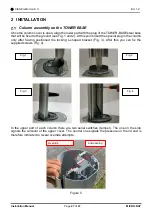
Страница 28: ...1 and 2 At this point insert the special plug in the column only after having positioned the locking L shaped bracket Fig 3 After this you can fix the supplied screws Fig 4 In the upper part of each c...

Страница 29: ...icated in the table below in the event of maintenance or replacement of a ray or part of it it will be necessary to follow mandatory the chart Incorrect positioning leads to system malfunctions No fur...

Страница 30: ...CIAS Elettronica S r l Ed 1 2 Installation Manual Page 29 of 47 MICRO RAY Column A Column B Figure 7 2 3 1 4 3 2 1 R4 A RX R3 A RX R2 A TX R1 A TX R4 B TX R3 B TX R2 B RX R1 B RX 4...

Страница 31: ...installed very close to the metal fences the fence itself must be carefully fixed so that the wind does not cause great movement Trees hedges bushes vegetation in general require particular attention...

Страница 32: ...aced at a distance ranging from 90cm to 160cm from the wall fence could be subject to phenomena that make a difficult alignment of the rays positioned at middle height In these cases it is preferable...

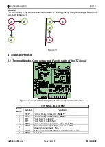
Страница 33: ...e TX circuit Figure 11 Topographical arrangement of the components in the circuit TERMINAL BLOCK MS1 Term Block Symbol Function 1 TMP Tamper Relay Contact C Note 1 2 TMP Tamper Relay Contact NC Note 1...

Страница 34: ...5 9 GND Ground FUNCTION SELECTOR No Symbol Function SW1 FUN Position 0 Normal Functionality Position 1 Reading Selection of the Modulation Channel Position 8 Reading Writing of the Barrier Number Posi...

Страница 35: ...Alarm Relay Contact NC 3 TMP Tamper Relay Contact C Note 1 4 TMP Tamper Relay Contact NC Note 1 5 FLT Fault Relay Contact C 6 FLT Fault Relay Contact NC 7 STBY Tamper Column Input Norm Closed to GND 8...

Страница 36: ...F D11 Indication of Tampering OFF D10 Indication of Fault OFF D9 Alignment and Adjustment Functions OFF D8 Alignment and Adjustment Functions OFF BUTTON Symbol Function S1 Board Reset Button ALIGNMENT...

Страница 37: ...RAY Interface circuit The MICRO RAY modules are all pre wired in the factory and connected to the MS1 terminal of the interface circuit positioned approximately in the middle of the column Figure 13...

Страница 38: ...8 V and GND respectively to the terminals 1 and 2 of terminal block CON3 of the interface circuit Power supply with optional IP DOORWAY kits As an alternative to the 13 8Vdc direct power supply it is...

Страница 39: ...er For the TX the outputs of the devices consist of two normally closed potential free relay contacts while for RX they are three They are used for signaling the following states ALARM RX TAMPERING RX...

Страница 40: ...a work parameter adjustment system and a test system which make installation operations particularly simple and without the need to use special tools It is necessary to align the Rays one at a time T...

Страница 41: ...V to terminals 1 and 2 of CON3 MICRO RAY Interface To optimize the alignment of each ray and set the parameters proceed as follows a Make a first Optical Visual alignment b Open the tamper removing th...

Страница 42: ...res both the value of the modulation channel and the present field value an alteration of the field at this time would therefore lead to an incorrect acquisition The acquisition of these parameters by...

Страница 43: ...ax 0 5m from the fence with the possibility of intrusion from the inside Installation example B Barrier positioned between 0 5m and 1m from the fence with intrusion from the outside Installation examp...

Страница 44: ...able and the ray to which the association is recommended All the rays can be set with all 5 applications The most suitable one with respect to the ray position is recommended below Setting Number Appl...

Страница 45: ...It analyses all the types of passage with greater reactivity see crawling slow fast walking run etc however increasing the risk of generating improper alarms due to the presence of vegetation along th...

Страница 46: ...Middle 0 3 High default 4 1 2 4 Read Write Barrier Number Carrying the function switch SW1 to position 8 it is possible to read and or set the barrier number Write barrier number Select a number from...

Страница 47: ...perature Check that the temperature is in the prescribed range 35C 65C Oscillator failure Tx ray Replace the Tx front end Faulty Tx ray Replace the Ray Faulty Led switched on on Rx side High and or lo...

Страница 48: ...le TX module supply current in supervision mA 65 Single RX module supply current in supervision mA 53 Intrusion alarm contact RX 100mA C NC Tamper contact TX RX 100mA C NC Fault contact TX RX 100mA C...

Страница 49: ...RAGGIO 2 RAGGIO 1 BARRIERA 3 RAGGIO 4 RAGGIO 3 RAGGIO 2 RAGGIO 1 BARRIERA 4 RAGGIO 4 RAGGIO 3 RAGGIO 2 RAGGIO 1 BARRIERA 5 RAGGIO 4 RAGGIO 3 RAGGIO 2 RAGGIO 1 BARRIERA 6 RAGGIO 4 RAGGIO 3 RAGGIO 2 RAG...

Страница 50: ...RAY 4 RAY 3 RAY 2 RAY 1 BARRIER 2 RAY 4 RAY 3 RAY 2 RAY 1 BARRIER 3 RAY 4 RAY 3 RAY 2 RAY 1 BARRIER 4 RAY 4 RAY 3 RAY 2 RAY 1 BARRIER 5 RAY 4 RAY 3 RAY 2 RAY 1 BARRIER 6 RAY 4 RAY 3 RAY 2 RAY 1 BARRIE...

Страница 51: ...NOTE...
Страница 52: ...elettriche ed elettroniche minimizzare l uso delle discariche per lo smaltimento dei prodotti e migliorare la qualit della vita evitando che sostanze potenzialmente pericolose vengano rilasciate nell...

Отзывы: