©
CIAS Elettronica S.r.l.
Ed. 1.2
Installation Manual
Page
41
of
47
MICRO-RAY
g) Loosen the fixing screw located on the upper side of the transmitting antenna joint (Tx), to
orient it in the horizontal plane and repeat the pointing operations.
Instead of using the button
S3
(Rx side), for the operation of acquiring the new signal level
received, it is possible to temporarily obscure the MW beam (for example by passing a
hand in front of the Tx head). Thanks to this feature, it is possible to command the
acquisition of the new signal without going to the receiver and press the
S3
button.
h) Once the best pointing has been achieved (therefore the maximum signal available), block
the horizontal movement on both the Rx and the Tx.
i) Unlock the vertical movement of the receiving antenna (Rx) by loosening the side screw
and orienting it upwards. Slowly rotate downwards searching for the maximum signal
repeating the pointing operations.
j) Unlock the vertical movement of the transmitting antenna (Tx) by loosening the side screw
and orienting it upwards. Slowly rotate downwards searching for the maximum signal
repeating the pointing operations.
k) After obtaining the best pointing, block the vertical movement both on the Receiver and on
the Transmitter.
l) Bring the function switch
SW1 to position 2
, making sure that there are no obstacles
during this operation.
In this phase, the barrier acquires both the value of the modulation channel and the present
field value, an alteration of the field at this time would therefore lead to an incorrect
acquisition.
The acquisition of these parameters by the receiver takes place a few seconds after the
button
S3
has been pressed.
The simultaneous switching on of the 2 red LEDs D8 and D9 indicates that the acquisition
of the channel, of the signal value and the measurement of the quality of the alignment
have started, after a few seconds if the channel and the signal value have been acquired
correctly, the 2 leds turn off and the buzzer is activated emitting a number of sounds
(BEEP) inversely proportional to the quality of the alignment according to the following
table:
Signal Quality
Buzzer
High quality
1 Beep
Good quality
2 Beeps
Poor quality
3 Beeps
Insufficient quality
4 Beeps
Very bad quality
5 Beeps or more
If the quality of the alignment is poor (or worse), repeat the entire alignment procedure,
making sure that there are no obstacles or disturbances in the protection field.
4.1.2.1 Application type setting, environmental disturbance filter and ray interruption
time
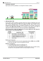
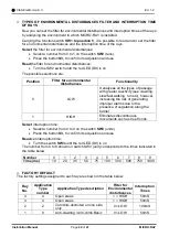
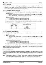
MICRO-RAY offers the possibility to choose among
5 settings "type of application",
2 settings "environmental disturbance filter" and 10 ray interruption times (from
10ms to 1 sec).
If you do not want to use the factory settings, you must first analyse the
environment in which the product will be installed and understand how to best set the
individual rays.
➢
INSTALLATION EXAMPLES
Below, for a better understanding, 4 possible types of installation are shown:
Содержание MICRO-RAY
Страница 51: ...NOTE...

