background image


Inspire Mini User Manual 

  V1.1 May 2014 

www.chroma-q.com 


2.5


Optics 

The Inspire Mini is built with Wide lens with a beam angle of approximately ~ 65°. 

2.6


Control 

The Inspire Mini can operate as a standalone unit or be controlled remotely via ANSI E1.11 USITT DMX512-A protocol. The 

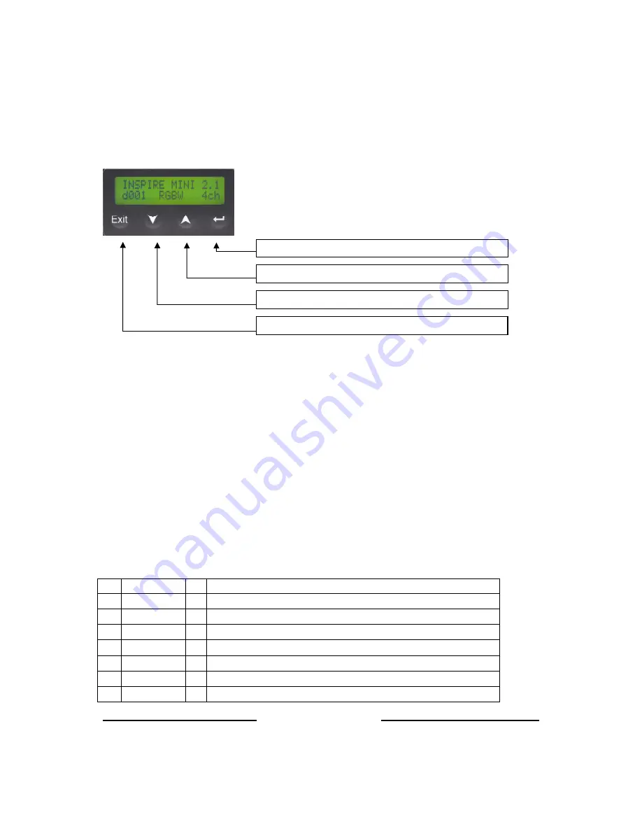
control functions can be accessed through the LCD display at the rear of the fixture with 4 push buttons.  


Power-Up Display: 

On power-up and home position, the display shows the Main Menu: 


model name 


software version 


the DMX address  


current assigned mode 


number of assigned channels 


Display Mode: 

The LCD is backlit when you access the menus. This will turn off when left undisturbed for 5 seconds.  

Control Modes:  

The  Inspire  Mini  consists  of  a  single  LED  engine  with  a  combination  of  6  Red  LEDs,  6  Green  LEDs,  6  Blue  LEDs  and  12 

Neutral  White  LEDs  for  a  total  of  30  LEDs.    Control  of  the  fixture  can  be  set  by  selecting  a  control  mode  from  the  list  of 

options below:  

No. 

Display 

Ch 

Description 

fxHSI 

4 x channels for E Hue, Saturation, Intensity  

sRGBW 

1 x Intensity Effects C Red, Green, Blue, White 

HSI    

Hue, Saturation & Intensity 

RGBW 

Red, Green, Blue, White 

11 

Look sel 

Look Select (Effects engine, programmable presets and user programmed Looks) 

12 

Mastr StndAlon   

Assigns the unit as Master in standalone operation 

13 

Slave StndAlon 


Assigns the unit as Slave in standalone operation 

Exit: Back to previous menu

Exit: Back to previous menu

Exit: Back to previous menu

Exit: Back to previous menu    

Up Arrow: Increases (+) the mode level or value

Up Arrow: Increases (+) the mode level or value

Up Arrow: Increases (+) the mode level or value

Up Arrow: Increases (+) the mode level or value    

Down Arrow: Decreases (

Down Arrow: Decreases (

Down Arrow: Decreases (

Down Arrow: Decreases (----) the mode level or

) the mode level or

) the mode level or

) the mode level or


value

value

value

value


Back Arrow: (Enter) Stores the menu choice

Back Arrow: (Enter) Stores the menu choice

Back Arrow: (Enter) Stores the menu choice

Back Arrow: (Enter) Stores the menu choice


Содержание Inspire Mini

Страница 1: ...Chroma Q Inspire Mini User Manual Version 1 1 May 2014 Software Version 2 1 PN 632 0704...

Страница 2: ...he above e by modification repair or service by anyone other than Chroma Q who has not applied for and been approved by Chroma Q to do such modification repair or service unless the Customer provides...

Страница 3: ...designed specifically for the lighting industry Regular maintenance should be performed to ensure that the products perform well in the entertainment environment If you experience any difficulties wi...

Страница 4: ...5 2 5 Optics 6 2 6 Control 6 2 7 DMX Protocol Inspire 11 2 8 Thermal Performance 13 3 3 3 3 Troubleshooting Troubleshooting Troubleshooting Troubleshooting 13 13 13 13 4 4 4 4 Specification Specifica...

Страница 5: ...Mini fixture is built with a single light engine featuring 30 high powered LEDs combination of white red green and blue Built with an internal power supply the fixture can operate as a standalone unit...

Страница 6: ...iling with the Inspire Ceiling Installation Kit which consists of the following items See Table Drawing below see Ceiling Installation Procedure on page 16 of this User Manual 1 Trim Ring Inspire Blac...

Страница 7: ...ol mode from the list of options below No Display Ch Description 1 fxHSI 7 4 x channels for Effects Hue Saturation Intensity 2 sRGBW 5 1 x Intensity Effects Channel Red Green Blue White 3 HSI 3 Hue Sa...

Страница 8: ...ck Back arrow Enter to select a control menu option Press and hold the Back Back Back Back arrow Enter to save the setting Press Exit Exit Exit Exit to return to the Main Menu Main Menu The Main Menu...

Страница 9: ...ected various output options can be selected OFF Fixture has no light output HOLD Fixture holds the last valid DMX state LOOK 01 31 Fixture snaps to the selected Look To set the option When DMX is Los...

Страница 10: ...the channel level Pressing Up Up Up Up or Down Down Down Down up to the far end will show the Mode at which the selected Look was programmed Proceed to edit the Mode the channels numbers and levels of...

Страница 11: ...Up or Down Down Down Down to select the Frequency 3 Press Enter Enter Enter Enter for 2 seconds to save The display returns to Technical and then the Main Menu Reset to Default To reset the fixture to...

Страница 12: ...rolling Single colour at 1 full spectrum at 255 Red Channel 3 Colour Step 0 255 Variable control of smoothness of colour scrolling Smoothest at 0 Most coarse is at 250 Rate will vary with scrolling sp...

Страница 13: ...1 4 Warm Colour Scroll 5 sec 12 15 5 Warm Colour Scroll 10 sec 16 19 6 Warm Colour Scroll 30 sec 20 22 7 Cold Colour Scroll 5 sec 23 25 8 Cold Colour Scroll 10 sec 26 27 9 Color Colour Scroll 30 sec 2...

Страница 14: ...cess of elimination First rule out the other field factors i e bad connections faulty cables and power supplies For technical support and or parts please contact your selling dealer or the offices lis...

Страница 15: ...512 A Cooling System Convection Operating Temperature 0 C to 40 C Construction Anodised aluminium extrusion Colour Black White Built In Hardware Mounting bracket IP Rating IP20 Approvals CISPR 22 200...

Страница 16: ...quires little maintenance However as the unit is likely to be used in a stage environment we recommend periodical internal inspection and cleaning of any resulting dust and cracked oil residue Do not...

Страница 17: ...im Ring is fastened on the 2 pem nuts of the Bracket Hook 3 T Nut 20 Economy 15S Nuts inserted into the extruded cavity between 2 extruded fins 4 Angle support ceiling mounting 2 angle bars that are m...

Страница 18: ...rds the external side of the enclosure Insert and hook the 2nd Bracket Hook to set onto the edges of the 2 straight extruded fins not curved on the opposite side 6 3 Attach the Angle Supports to the T...

Страница 19: ...5 Put the Cap back Put the cap back and fasten with 2 x M3 FH screws 5 5 in lb torque 6 6 Fasten the Trim Ring to the 2 Bracket Hooks on the fixture Adjust the trim height then fasten with the 4 flan...

Страница 20: ...May 2014 www chroma q com 6 8 Install the fixture onto the ceiling Turn the fixture with the Trim Ring and Angle Supports lens side down Fasten the angle supports onto the appropriate ceiling infrast...

Отзывы: