background image

20

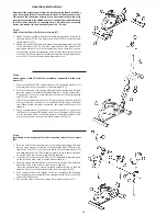
Assembly Instructions

Remove all the separate parts from the packaging, lay them on the floor
and check roughly that all are there on the base of the assembly steps.
Please note that a number of parts are connected directly to the main 
frame preassembled. In addition, there are several other individual parts
that have been attached to separate units. This will makes assembly 
easier and quicker for you. Assembly time: 40 - 50 min.

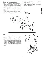
Step 1:

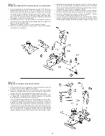
Attach the stabilizer (59+86) at main frame (57).

1.   Attach the front foot (86) with preassembled transportation roller (85) to 

the main frame (57). Do this with screws M8x25 (99), washers (87) and 
spring washers (14).

2.  Attach the rear foot (59) with preassembled height adjustable caps (58) 

to the main frame (57). Do this with screws M8x25 (99), washers (87) 
and spring washers (14). After assembly has been complete, you can 
compensate for minor irregularities in the floor by turning the wheel at 
foot caps (58). The equipment should be set up that the equipment does 
not move of its own accord during a training session.

Step 2:

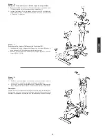
Connection of cables (19+94) and assembly of support (92) at the main 
frame (57). 

1.   Place screws M8x20 (56), curved washers (91) and spring washers (14) 

accessibly beside the front part of the main frame (57).

2.  Place the lower end of the support (92) against the main frame (57) and 

push the support cover (89) with rubber ring (90) onto the support (92). 
Plug the ends of the two computer cable harnesses (19+94) projecting 
from (57+92) together.


(Note: The computer cable harness (19) projecting from the support (92) 
must not slide into the tube, as it is required for later steps of installa-
tion.) When joining the tubes, ensure that the cable connection will not 
trapped.

3.  Put one spring washer (14) and one curved washer (91) on each screw 

(56). Push the screws (56) through the holes in the support (92), screw 
into the threaded holes of the main frame (57) and tighten lightly. (This 
screw connection point will screw firmly at least in Step 4.)

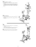
Step 3:

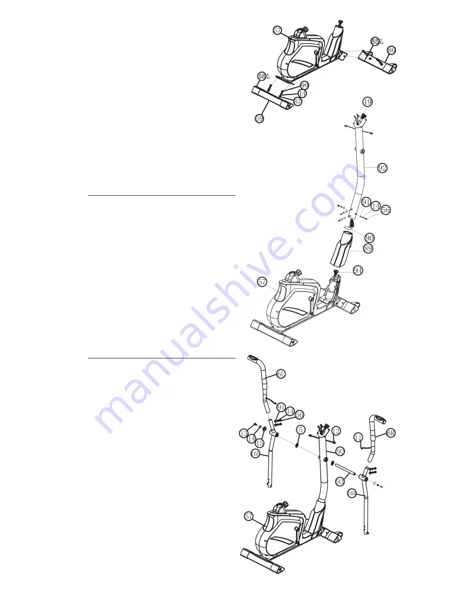
Installation of the handgrips (6) with connecting tubes (16) at support 
(92).

1.   Push the axle (93) into the middle position at handlebar support (92) and 

put one wave washer (5) and the connecting tube right (16R) onto  the 
right axles’ end (93). Put on the screw M8x20 (13) a spring washer (14) 
and a big washer 8//38 (15) and tighten it firmly. (Note: Right is specified 
as viewed standing on the machine during training.)

2.  Install the left connection tube (16L) incl. all additionally required parts 

on the left hand side of the machine as described in 1.

3.  Push the hand grips (6L+6R) onto the connecting tubes (16L+16R) and  

adjust the holes in the tubes so that they are aligned.


(Note: the handgrip bars must be aligned after assembly so that the 
upper ends are inclined outwards (away from the support (92)).

4.  Push the bolt M8x20 (56) through the holes and tighten the handgrip 

bars (6) with curved washers (91) and spring washers (14) at connection 
tubes (16L+16R) firmly.

5.  Connect the pulse connection cables (12) with pulse cables (11).

Содержание AL 4

Страница 1: ...ngsanleitung für Bestell Nr 1611 Notice de montage et d utilisation du No de commande 1611 Assembly and exercise instructions for Order No 1611 Montage en bedieningshandleiding voor Bestellnummer 1611 GB D F NL RU Инструкция по монтажу и эксплуатации заказа 1611 ...

Страница 2: ...n Personen benutzt werden Dieses Gerät kann von Kindern ab 8 Jahren und Personen mit eingeschränkten physischen sensorischen oder geistigen Fähigkeiten oder Mangel an Erfahrung und Wissen verwendet werden wenn eine angemessene Aufsicht oder ausführliche Anleitung zur sicheren Benutzung des Gerätes sowie Aufklärung der evtl damit verbundenen Gefahren verstanden wurde Kinder dürfen nicht mit dem Hei...

Страница 3: ...3 Montageübersicht Assembly overview Aperçu de l Assemblée Montage overzicht Обзор Ассамблея D GB F NL RU ...

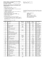
Страница 4: ...BT 11 Pulskabel 2 6 36 1611 09 BT 12 Pulsverbindungskabel 2 1 11 36 1611 10 BT 13 Innensechskantschraube M8x20 2 93 39 9886 CR 14 Federring für M8 14 13 56 99 39 9864 VC 15 Unterlegscheibe 8 36 2 13 39 10166 16L Verbindungsrohr links 1 6L 31 33 1611 07 WS 16R Verbindungsrohr rechts 1 6R 31 33 1611 08 WS 17 Schraube 4 5x25 13 16 46 36 9825338 BT 18L 1 Abdeckung links vorne 1 16L 18L 2 36 1611 11 BT...

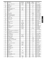
Страница 5: ...hskantschraube M8x20 8 16 57 92 39 9886 CR 57 Grundrahmen 1 33 1611 01 WS 58L Fußkappe hinten links 1 59 36 1611 18 BT 58R Fußkappe hinten rechts 1 59 36 1611 19 BT 59 Hinterer Fuß 1 57 33 1611 04 WS 60 Achsmutter schmal M10x1 25 2 64 39 9820 61 Sicherungsring C10 2 64 36 1611 20 BT 62 Kugellager 6000 2RS 2 63 36 1611 21 BT 63 Schwungrad 1 61 62 33 1611 13 SI 64 Schwungradachse 1 57 63 36 1611 25 ...

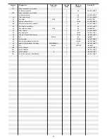
Страница 6: ...ffrohrachse 1 16 92 33 1611 15 SI 94 Motorkabel 1 19 96 36 1507 14 BT 95 Schraube M5x10 4 96 39 9907 96 Stellmotor 1 57 94 36 1507 07 BT 97 Netzanschlussbuchse 1 16L 98 36 1507 08 BT 98 Netzgerät 9Volt DC 500mA 1 97 36 1507 22 BT 99 Innensechskantschraube M8x25 4 59 57 86 39 10455 100 Multiwerkzeug 1 1 36 9107 27 BT 101 Multiwerkzeug 2 1 36 1611 33 BT 102 Innensechskantschlüssel 6 2 36 9107 28 BT ...

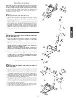
Страница 7: ...gen zusammenstecken Achtung Das oben aus dem Stützrohr 92 ragende Ende des Computerkabelstrangs 19 darf nicht in das Rohr rutschen da es zur weiteren Montage noch benötigt wird Ebenso darauf achten dass beim Zusammenstecken der Rohre die Kabelverbindung nicht eingequetscht wird 3 Auf die Schrauben 56 je einen Federring 14 und eine gebogenen Unterlegscheibe 91 stecken und das Stützrohr 92 auf den G...

Страница 8: ...fest 2 Legen Sie den Sattelschlitten 22 in die Aufnahme am Sattelstützrohr 26 und befestigen Sie diesen in gewünschter horizontaler Stellung mit der Sterngriffmutter 25 der Unterlegscheibe 24 und dem Befestigungsteil 23 3 Schieben Sie das Sattelstützrohr 26 in die entsprechende Aufnahme am Grundrahmen 57 und sichern Sie diese in gewünschter Position mittels des Schnellverschlusses 28 Der Schnellve...

Страница 9: ...er 1 auf die Computeraufnahme oben am Stützrohr 92 auf und befestigen Sie ihn mittels der Schrauben 2 welche sich in der Rückseite des Computers befinden Bitte achten Sie darauf dass die Kabel bei der Montage des Computers nicht eingeklemmt werden Schritt 8 Kontrolle 1 Alle Verschraubungen und Steckverbindungen auf ordnungsgemäße Montage und Funktion prüfen Die Montage ist hiermit beendet 2 Wenn a...

Страница 10: ...geschraubt ist Ziehen Sie nicht das Sattelstützrohr über die maximale Position heraus und verstellen Sie keine Position während Sie auf dem Trainingsgerät sitzen Eine biomechanisch optimale Sitzposition gewährleistet eine optimale Kraftübertragung Ziel ist es dass die vorhandene Kraft größtmöglich auf den Pedalen ankommt und die Muskulatur im optimalen Wirkungsbereich arbeitet Die Sitzposition bee...

Страница 11: ...auf Seite 2 angemerkt zulässig ist Stufe 30 UPM WATT 40 UPM WATT 50 UPM WATT 60 UPM WATT 70 UPM WATT 1 16 25 35 48 62 2 18 28 40 55 71 3 20 32 45 62 80 4 22 35 51 69 89 5 24 39 56 76 98 6 26 42 61 83 107 7 28 46 66 89 115 8 30 49 71 96 124 9 32 53 77 103 133 10 34 56 82 110 142 11 36 60 87 117 151 12 38 63 92 124 160 13 40 66 97 131 169 14 42 70 102 138 178 15 44 73 108 145 187 16 46 77 113 152 19...

Страница 12: ...te kann der Widerstand beliebig eingestellt werden Alle ak tuellen Trainingsdaten werden angezeigt Sie befinden sich im manuellen Programm Training mit Vorgabe von Daten 1 Einschalten durch Einstecken des Netzgerätes Das Display zeigt einen User U1 U4 zur Auswahl an und kann durch die Drehtaste ausgewählt werden Bestätigen des Benutzers U1 U4 mit der F Taste 2 Dann können persönlichen Daten für di...

Страница 13: ...Hier können Sie Ihre individuelle Watt Vorgabe mittels der Drehtaste eingeben Innerhalb eines gewissen Toleranz bereiches wird der Tretwi derstand dann automatisch un abhängig von der Trittfrequenz vom Com puter nachgeregelt so dass Sie sich immer in der vorgegebenen Zone befinden Voreinstellung ist 120Watt In 5Watt Schritten kann der Wert von 10 bis 350 Watt verändert werden Der eingege bene WATT...

Страница 14: ...e winde des Schnellverschlusses geben Störungsbeseitigung Wenn Sie die Funktionsstörung nicht anhand der aufgeführten Informationen beheben können so kontaktieren Sie Ihren Händler oder den Hersteller Problem Mögliche Ursache Lösung Der Computer schaltet sich durch Drücken einer Taste nicht ein Kein Netzteil ein gesteckt oder die Steckdose führt keine Spannung Überprüfen Sie ob das Netzge rät ordn...

Страница 15: ... Körpertemperatur und die Sauerstoffzufuhr langsam gesteigert werden Dieses ist durch gymnastische Übungen über eine Dauer von fünf bis zehn Minuten möglich Danach sollte das eigentliche Training Trainings Phase beginnen Die Trainingsbelastung sollte erst einige Minuten gering sein und dann für eine Periode von 15 bis 30 Minuten so gesteigert werden daß sich der Puls im Bereich zwischen 70 und 85 ...

Страница 16: ... from 8 years and above and persons with reduced physical sensory or mental capabilities or lack of experience and knowl edge if they have been given supervision or instruction concerning use of the appliance in a safe way and understand the hazards involved Children shall not play with the appli ance Cleaning and user maintenance shall not make by children without supervision Take suitable measur...

Страница 17: ...Hand grip right 1 16R 33 1611 06 WS 7 Screw M4x25 2 10 36 9111 38 BT 8 End cap 2 6 36 1611 07 BT 9 Hand wrapping 2 6 36 1611 08 BT 10 Hand pulse sensor 2 6 36 9126 06 BT 11 Pulse cable 2 6 36 1611 09 BT 12 Pulse connection cable 2 1 11 36 1611 10 BT 13 Allen bolt M8x20 2 93 39 9886 CR 14 Spring washer for M8 14 13 56 99 39 9864 VC 15 Washer 8 36 2 13 39 10166 16L Connection tube left 1 6L 31 33 16...

Страница 18: ...0 8 16 57 92 39 9886 CR 57 Main Frame 1 33 1611 01 WS 58L Rear stabilizer cap left 1 59 36 1611 18 BT 58R Rear stabilizer cap right 1 59 36 1611 19 BT 59 Rear stabilizer 1 57 33 1611 04 WS 60 Axle nut small M10x1 25 2 64 39 9820 61 Safety clip C10 2 64 36 1611 20 BT 62 Bearing 6000 2RS 2 63 36 1611 21 BT 63 Flywheel 1 61 62 33 1611 13 SI 64 Flywheel axle 1 57 63 36 1611 25 BT 65 Chain adjuster set...

Страница 19: ...Handle bar post 1 57 33 1611 02 WS 93 Handgrip axle 1 16 92 33 1611 15 SI 94 Motor cable 1 19 96 36 1507 14 BT 95 Drill screw M5x10 4 96 39 9907 96 Motor 1 57 94 36 1507 07 BT 97 DC cable 1 16L 98 36 1507 08 BT 98 Adapter 9Volt DC 500mA 1 97 36 1507 22 BT 99 Allen bolt M8x25 4 59 57 86 39 10455 100 Combination wrench 1 36 9107 27 BT 101 Open end wrench 1 36 1611 33 BT 102 Allen key wrench 2 36 910...

Страница 20: ...Plug the ends of the two computer cable harnesses 19 94 projecting from 57 92 together Note The computer cable harness 19 projecting from the support 92 must not slide into the tube as it is required for later steps of installa tion When joining the tubes ensure that the cable connection will not trapped 3 Put one spring washer 14 and one curved washer 91 on each screw 56 Push the screws 56 throug...

Страница 21: ...dle support 26 1 Push the saddle 20 with saddle bracket into the saddle slide 22 and tight it up in desired position 2 Place the saddle slide 22 into the holder of saddle support 26 set it at the desired position and screw it onto the saddle support 26 by screw 23 washer 24 and star grip nut 25 3 Push the saddle support tube 26 into the matching locator in the main frame 57 set it at the desired p...

Страница 22: ...essary later Step 7 Attach the AC adaptor 98 1 Please insert the plug of adaptor 98 to the power plug 97 at end of chain cover 2 Please insert the plug of adaptor 98 to the jack of wall power 230V 50Hz Step 6 Attach the computer 1 at support 92 1 Put the plug of connection cable 19 into the plug from computer 1 backside 2 Insert the plug of pulse connection cables 12 to the jack of the computer 1 ...

Страница 23: ... desired position and tighten them after adjustment again firmly To avoid any problems such as back knee pain or numbness in the feet through bad seat position on the bike the maintenance of a proper adjust ment of the saddle and handlebar we strongly recommend Mount Use Dismount Mount a After the seat is adjusted to properly position insert your foot into retaining strap of pedal step on the peda...

Страница 24: ...le LEVEL 30 RPM WATT 40 RPM WATT 50 RPM WATT 60 RPM WATT 70 RPM WATT 1 16 25 35 48 62 2 18 28 40 55 71 3 20 32 45 62 80 4 22 35 51 69 89 5 24 39 56 76 98 6 26 42 61 83 107 7 28 46 66 89 115 8 30 49 71 96 124 9 32 53 77 103 133 10 34 56 82 110 142 11 36 60 87 117 151 12 38 63 92 124 160 13 40 66 97 131 169 14 42 70 102 138 178 15 44 73 108 145 187 16 46 77 113 152 196 17 48 80 118 158 204 18 50 84 ...

Страница 25: ...ough pressing START STOP key With UP DOWN turnkey you can adjust the resistance level All exercise data will show on display You are in manual program Exercising with enter data 1 Plug in power supply computer will power on and display show all seg ments on LCD for 2 sec then LCD display flash user U1 U4 Select user by turning UP DOWN turnkey Confirm setting by pressing MODE F key 2 Put in individ...

Страница 26: ...5 90 or TAG TAR GET H R default 100 3 Turn UP DOWN turnkey to preset workout TIME 4 Press START STOP key to start or stop workout Press RESET L key to reverse to main menu 5 During workout if no hand pulse detected console will stop to reminder Watt unabhängiges Wattprogramm 1 Turn UP DOWN turnkey to select workout program choose WATT and press MODE F key to enter 2 Turn UP DOWN turnkey to preset ...

Страница 27: ...y oil at the pedal bearings left and right to the thread of quick release for saddle support Troubleshooting If you cannot solve the problem with the following information please contact the authorized service center Problem Possible Cause Solution Computer has no value at Dis play if you press any key No power adapter is well plugged or wall power is without power Check that the power adapter is ...

Страница 28: ... to ten minutes Then the actual training training phase should begin The training exertion should be relatively low for the first few minutes and then raised over a period of 15 to 30 minutes such that the pulse rate reaches the region of between 70 to 85 of the maximum pulse rate In order to support the circulation after the training phase and to prevent aching or strained muscles later it is nec...

Страница 29: ...port ne sont pas des jouets Ce dispositif peut être utilisé par des enfants âgés de 8 ans et les personnes ayant des capacités physiques sensorielles ou mentales réduites ou manque d expérience et de connaissances si approprié surveillance ou d instructions détaillées pour l utilisation sûre de l appareil ainsi que l éducation des dangers éventuellement associés a été entendu Les enfants ne peuven...

Страница 30: ... 1611 03 BT 2 Vis M5x10 4 1 92 39 9903 3 Bouchon de sécurité 12 3 6 92 36 9134 22 BT 4 Camp du plastique 19x38 6 16 92 36 9825328 BT 5 Rondelle 19 38 5 2 93 36 9925114 BT 6L Poignée de maintien gauche 1 16L 33 1611 05 WS 6R Poignée de maintien droite 1 16R 33 1611 06 WS 7 Vis M4x25 2 10 36 9111 38 BT 8 Bouchon 2 6 36 1611 07 BT 9 Revêtement de poignée 2 6 36 1611 08 BT 10 Unité à poignée de mesure...

Страница 31: ...3 53 36 1508 11 BT 55 Ecrou d axe M10x1 25 1 64 39 9820 SW 56 Vis M8x20 8 16 57 92 39 9886 CR 57 Châssis 1 33 1611 01 WS 58L Capuchons de protection égalisation de la hauteur gauche 1 59 36 1611 18 BT 58R Capuchons de protection égalisation de la hauteur droite 1 59 36 1611 19 BT 59 Tube de pied arrière 1 57 33 1611 04 WS 60 Ecrou d axe étroit M10x1 25 2 64 39 9820 61 Bague de sécurité C10 2 64 36...

Страница 32: ...ondelle de caoutchouc 1 89 36 1611 32 BT 91 Rondelle intercalaire 8 19 8 56 39 9966 CR 92 Tube support 1 57 33 1611 02 WS 93 Axe de poignée 1 16 92 33 1611 15 SI 94 Câble de connexion du moteur 1 19 96 36 1507 14 BT 95 Vis M5x10 4 96 39 9907 96 Servomoteur 1 57 94 36 1507 07 BT 97 Câble d alimentation avec douille 1 16L 98 36 1507 08 BT 98 Appareil d alimentation électrique 9V DC 500mA 1 97 36 150...

Страница 33: ...ux de câbles de l ordinateur ensemble 19 94 dépassant du cadre de base 57 et du tube support 92 Attention L extrémité du faisceau de câble de l ordinateur 19 dépassant de la partie supérieure du tube de support 92 ne doit pas glisser dans le tube car elle sera indispensable pour poursuivre le montage 3 Placer une rondelle élastique bombée 14 ainsi qu une rondelle 91 sur chacune des vis 56 Introdui...

Страница 34: ...e 26 dans le support prévu à cet effet du corps de l appareil 57 ajustez la position désirée et bloquez la en insérant la vis à poignée en croix 28 et la serrant à fond Pour desserrer la fermeture rapide 28 il suffit simplement de la tourner ce qui permet ensuite de la tirer pour pouvoir débloquer le dispositif d arrêt de la hauteur et modifier la hauteur de la selle Lorsque la fermeture rapide 28...

Страница 35: ...mander des pièces de rechange Etape n 7 Branchement de l appareil d alimentation électrique 98 1 Introduisez la fiche de l appareil d alimentation électrique 98 dans la prise adéquate 97 à l extrémité arrière du revêtement 2 Enfichez ensuite l appareil d alimentation électrique 98 dans une fiche femelle 230V 50Hz Etape n 6 Montage de l ordinateur 1 sur le tube de support de support 92 1 Branchez l...

Страница 36: ...n désirée et serrez les après ajustement de nouveau fermement Pour des problèmes tels que maux de dos genou ou engourdissement dans les pieds empêché par un manque de place assise sur la moto le maintien d un bon réglage de la selle et le guidon est fortement recommandée Monter utiliser descendre Monter a Après avoir réglé la selle dans la position désirée placez votre pied dans la bande de la péd...

Страница 37: ...n page 29 est autorisée NIVEAU 30 RPM WATT 40 RPM WATT 50 RPM WATT 60 RPM WATT 70 RPM WATT 1 16 25 35 48 62 2 18 28 40 55 71 3 20 32 45 62 80 4 22 35 51 69 89 5 24 39 56 76 98 6 26 42 61 83 107 7 28 46 66 89 115 8 30 49 71 96 124 9 32 53 77 103 133 10 34 56 82 110 142 11 36 60 87 117 151 12 38 63 92 124 160 13 40 66 97 131 169 14 42 70 102 138 178 15 44 73 108 145 187 16 46 77 113 152 196 17 48 80...

Страница 38: ... et commencez l entrainement Il ya un écran de démarrage bref et puis la sélection de l utilisateur Appuyant sur la touche START STOP La résistance peut être ajustée a la touche souhaitée Tournez la touche de tours Toutes les données de formations actuelles sont affichées Vous êtes dans le programme manuel Formation à la spécification de données 1 Mettre en branchant l adaptateur secteur et commen...

Страница 39: ... défaut du temps TIME distance DISTANCE consommation d énergie CALORIES et pouls PULSE en appuyant sur les touches F et Appuyez sur la touche START STOP pour démarrer le programme d emploi PROGRAM Programmes de formation P1 12 12 programmes de formation différents P1 P12 pour divers formation avec les profils de formation différents Tourner la touche de tours clés du programmes P1 P12 appelé et ch...

Страница 40: ...n les roulements de la pédale gauche et à droite et sur les filets de la libération rapide Corrections Si vous ne pouvez pas résoudre en utilisant les informations énumérées à l dysfonctionnement s il vous plaît contactez votre revendeur ou fabricant Problème Cause Possible Solution L ordinateur ne s allume pas en appuyant sur un bouton Aucun adapta teur de courant est insérée ou la prise n est pa...

Страница 41: ...ible en effectuant de la gymnastique pendant cinq à dix minutes L entraînement proprement dit phase d entraînement devant commen cer ensuite Choisir une faible résistance pendant quelques minutes puis accroître entre 15 et 30 minutes de sorte que le pouls se situe entre 70 et 85 de son maximum Afin de faciliter la circulation après la phase d entraînement et d éviter des courbatures ou des muscles...

Страница 42: ...assing geven en een slipvrije zool hebben 12 Waarschuwing Wanneer duizeligheid misselijkheid borstpijn en an dere abnormale symptomen ondervonden worden de training vroegtijdig beëindigen en u tot een geschikte geneesheer wenden 13 Over het algemeen geldt dat sporttoestellen geen speelgoed zijn Dit apparaat kan worden gebruikt door kinderen van 8 jaar en personen met verminderde lichamelijke zintu...

Страница 43: ...eeldingsnr 1 Computer 1 92 36 1611 03 BT 2 Schroef M5x10 4 1 92 39 9903 3 Kabelvaszet 12 3 6 92 36 9134 22 BT 4 Kunstoflager 19x38 6 16 92 36 9825328 BT 5 Onderlegplaatje 19 38 5 2 93 36 9925114 BT 6L Handgreep links 1 16L 33 1611 05 WS 6R Handgreep rechts 1 16R 33 1611 06 WS 7 Schroef M4x25 2 10 36 9111 38 BT 8 Ronde dop 2 6 36 1611 07 BT 9 Stuur overtrek 2 6 36 1611 08 BT 10 Handpolseenheid 2 6 ...

Страница 44: ... 54 Schijf golfen 10 15 3 53 36 1508 11 BT 55 Asmoer M10x1 25 1 64 39 9820 SW 56 Binnenzeskantschroef M8x20 8 16 57 92 39 9886 CR 57 Basisframe 1 33 1611 01 WS 58L Voet met hoogtecompensatie links 1 59 36 1611 18 BT 58R Voet met hoogtecompensatie rechts 1 59 36 1611 19 BT 59 Achterste voetbuis 1 57 33 1611 04 WS 60 Asmoer smal M10x1 25 2 64 39 9820 61 Vastzetring C10 2 64 36 1611 20 BT 62 Kogellag...

Страница 45: ... 9966 CR 92 Steunbuis 1 57 33 1611 02 WS 93 Greep as 1 16 92 33 1611 15 SI 94 Motorkabel 1 19 96 36 1507 14 BT 95 Schroef M5x10 4 96 39 9907 96 Stelmotor 1 57 94 36 1507 07 BT 97 Spanningsverzorgingkabel 1 16L 98 36 1507 08 BT 98 Nettoestel spanningsverzorging 9Volt DC 500mA 1 97 36 1507 22 BT 99 Binnenzeskantschroef M8x25 4 59 57 86 39 10455 100 Multi Werktuig 1 1 36 9107 27 BT 101 Multi Werktuig...

Страница 46: ...eunbus 92 2 Verbind de stekkers van de stelmotor kabel 94 en verbindingskabel 19 met elkaar 3 Schuif de steunbus 92 op het basisframe 57 let erop dat er geen kabelverbinding gekneld geraakt Speld op iedere schroef 56 een veerring 14 en een onderlegplaatje 91 en schroef ze eerst allemaal met de hand vast Deze schroefverbinding zal in ieder geval bij stap 4 stevig worden aangedraaid Stap 3 Montage v...

Страница 47: ...moer 25 de tussenring 24 en het bevestigingsschroef 23 3 Plaats de zadelbuis 26 in de bijbehorende buis van het onderstel 57 Stel de gewenste positie in en borg deze door de bout met snelsluiting 28 te plaatsen en vast te draaien de snelsluiting 28 moet losgemaakt worden door deze een beetje te draaien en daarna kan getrokken wor den om de hoogtevastzetting vrij te geven en de hoogte van het zadel...

Страница 48: ...an reserve onderdelen nodig heeft Stap 7 Aansluiting van het nettoestel 98 1 Steek de stekker van het nettoestel 89 in de desbetreffende bus 97 op het achterste uiteinden van de bekleding 2 Steek daarna het nettoestel 89 in een contactdoos 230V 50Hz Stap 6 Montage van de computer 1 aan het steunbuis 92 1 Neemt u de computer 1 en steekt u de verbindingskabel 19 en de pols verbindings kabel 12 in de...

Страница 49: ...raai ze na aanpassing opnieuw stevig Om problemen zoals rug knie pijn of gevoelloosheid in de voeten voorko men door een gebrek aan zitpositie op de fiets het behoud van een juiste afstelling van het zadel en het stuur wordt sterk aanbevolen De Opstappen Gebruiken en Afstappen Opstappen a Nadat u de zitting op de juiste hoogte hebt afgesteld plaatst u uw voet op de voetsteun onder het riempje en h...

Страница 50: ...p pagina 42 is toegestaan LEVEL 30 RPM WATT 40 RPM WATT 50 RPM WATT 60 RPM WATT 70 RPM WATT 1 16 25 35 48 62 2 18 28 40 55 71 3 20 32 45 62 80 4 22 35 51 69 89 5 24 39 56 76 98 6 26 42 61 83 107 7 28 46 66 89 115 8 30 49 71 96 124 9 32 53 77 103 133 10 34 56 82 110 142 11 36 60 87 117 151 12 38 63 92 124 160 13 40 66 97 131 169 14 42 70 102 138 178 15 44 73 108 145 187 16 46 77 113 152 196 17 48 8...

Страница 51: ...ruiker selectie Start de training door op de START STOP toets zonder gebruiker selectie De weerstand kan worden aangepast naar wens draai aan de draai toets Alle huidige trainingsgegevens worden weergegeven Je bent in de handmatige programma Trainen met specificatie van gegevens 1 Steek in de adapter in een contactdoos Het display toont vervolgens de gebruiker selectie U1 U4 gebruikersprogramma en...

Страница 52: ...rogramma Hier kunt u uw individuele watt instelling te openen binnen zekere tole rantie bereik de trapweerstand automatisch ongeacht bepalen door de cadans van de computer zodat u altijd in de aangegeven zone Stan daardoptie van Watt door druken op de F toets Voraf ingestelde Watt waard 120 Watt kun u in stappen van 5 watt waarde van 10 350 watt kan worden gewijzigd Gebruik de draaitoets op de wat...

Страница 53: ... schroefdraad van de zadel sluitschroef Fixes Als u niet kunt oplossen met behulp van de genoemde storing informatie kunt u contact opnemen met uw dealer of Fabrikant Probleem Mogelijke oor zaak Oplossing De computer wordt niet inge schakeld door het indrukken van een knop Geen stroom ad apter is geplaatst of de socket is niet leven Controleer of de adapter correct is aangesloten eventueel met een...

Страница 54: ... beginnen De trainingsbelasting moet de eerste minuten laag zijn en dan gedurende een periode van 15 tot 30 minuten zo toenemen dat de hartslag zich tussen de 70 en 85 van de maximale hartslag bevindt Om de bloedsomloop na de trainingsfase te ondersteunen en om spierpijn of verrekte spieren te voorkomen moet de trainingsfase door een cooling down worden gevolgd Hierbij moeten vijf tot tien minuten...

Страница 55: ...фиксацию заново настроенного положения 10 Если в руководстве не указано иного то тренажером может пользоваться только один человек Время тренировки не должно было превосходить в целом 60 Min ежедневно 11 Необходимо носить тренировочную одежду и обувь которые подходят для оздоровительной тренировки на тренажере Одежда должна такой чтобы по своей форме например длине она не могла зацепиться во время...

Страница 56: ...бственные параметры время дистанция расход калорий пульс и нагрузка в ваттах Извещение о превышении заданных параметров Фитнесс тест Наименование Размеры в мм Кол во Монтируется на ЕТ картинки штук 1 Компьютер 1 92 36 1611 03 BT 2 Болт M5x10 4 1 92 39 9903 3 Предохранитель кабеля 12 3 6 92 36 9134 22 BT 4 Пластмассовый подшипник 19x38 6 16 92 36 9825328 BT 5 Подкладная шайба 19 38 5 2 93 36 992511...

Страница 57: ...17 22 2 82 39 10135 50 Шарикоподшипник 6003 2RS 2 57 82 36 9806214 BT 51 Болт M6x15 1 53 39 9860 52 Подкладная шайба 6 14 1 51 39 9863 53 Натяжной ролик 24x37x20 5 1 57 36 9806216 BT 54 Гнутая подкладная шайба 10 15 3 53 36 1508 11 BT 55 Осевая гайка M10x1 25 1 64 39 9820 SW 56 Болт M8x20 8 16 57 92 39 9886 CR 57 Основная рама 1 33 1611 01 WS 58L Колпачок эксцентрика слева 1 59 36 1611 18 BT 58R К...

Страница 58: ...36 1611 28 BT 90 Резиновое кольцо 1 89 36 1611 32 BT 91 Изогнутая подкладная шайба 8 19 8 56 39 9966 CR 92 Опорной трубы 1 57 33 1611 02 WS 93 Ось 1 16 92 33 1611 15 SI 94 Кабель серводвигателя 1 19 96 36 1507 14 BT 95 Болт M5x10 4 96 39 9907 96 Серводвигатель 1 57 94 36 1507 07 BT 97 Электрокабель 1 16L 98 36 1507 08 BT 98 Блок питания 9Volt DC 500mA 1 97 36 1507 22 BT 99 Болт M8x25 4 59 57 86 39...

Страница 59: ...мпьютерного кабеля 19 не должен западать в трубу т к он Вам еще понадобится при последующем монтаже Также обратите внимание на то чтобы при соединении труб компьютерные кабели не были зажаты 3 Наденьте на каждый болт 56 по одной пружинной шайбе 14 и одной подкладной шайбе 91 и вставьте опорную трубу 92 в основную раму 57 Вставьте винты 56 через отверстия а не затянуть Это происходит только на этап...

Страница 60: ...с помощью грибковой шайбы 25 подкладной шайбы 24 и болта 23 3 Вставьте манжету опорную трубу седла 26 и соответствующее крепление на основной раме 57 и зафиксируйте ее в желаемом положении с помощью быстродействующего затвора 28 Быстродействующий затвор 28 должен быть немного ослаблен посредством небольшого поворачивания после этого он вытягивается для освобождения фиксации высоты и высота седла м...

Страница 61: ...азов запасных частей Шаг 7 Подключение блока питания 98 1 Вставьте штекер блока питания 98 в соответствующее гнездо 97 на заднем конце обшивки 2 Затем вставьте блок питания 98 в розетку 230V 50Hz Шаг 6 Монтаж компьютера 1 на опорную трубу 92 1 Вставьте соединительный кабель 19 и кабель датчика пульса 12 в соответствющие гнезда компьютера 1 2 Вставьте компьютер 1 в опорной трубе 92 обратите внимани...

Страница 62: ...енения положения руля ослабьте быстродействующий затвор измените положе ние руля и снова крепко заверните быстродействующий затвор Чтобы предотвратить возможные боли в коленях и в спине из за неправильного положения тела мы рекомендуем уделить внимание правильному положению седла и руля Садиться и спускаться с тренажера Садиться на тренажер После установления правильной высоты седла возьмитесь за ...

Страница 63: ...TT 70 RPM WATT 1 16 25 35 48 62 2 18 28 40 55 71 3 20 32 45 62 80 4 22 35 51 69 89 5 24 39 56 76 98 6 26 42 61 83 107 7 28 46 66 89 115 8 30 49 71 96 124 9 32 53 77 103 133 10 34 56 82 110 142 11 36 60 87 117 151 12 38 63 92 124 160 13 40 66 97 131 169 14 42 70 102 138 178 15 44 73 108 145 187 16 46 77 113 152 196 17 48 80 118 158 204 18 50 84 123 165 213 19 52 87 128 172 222 20 54 91 134 179 231 ...

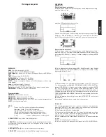
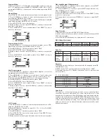
Страница 64: ...жание жира тела Определяет содержания жира тела по данным внесенным в индивидуальных программах U1 U 4 Описание функций Ввод в эксплуатацию Тренировка без ввода показателей Вставьте штекер блока питания в розетку На дисплее появится следу ющее изображение и сразу после этого Вы сможете выбрать пользователя Посредством нажатия на клавишу START STOP СТАРТ СТОП начни те тренировку С помощью клавиш во...

Страница 65: ...аммы соответствующий 55 75 или 90 целевой пульс Этот показатель выводится на дисплее Частота вращения педалей контролируется и поддерживается компьютером для того чтобы оставаться в пределах целевого пульса При дости жении максимального целевого пульса раздается световой и звуковой сигнал Возможность задавать собственный параметр ВРЕМЯ посред ством нажатия на клавишу F Нажатием на клавишу START ST...

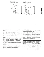
Страница 66: ...ли проблема не может быть решена с помощью нижестоящих указаний пожалуйста обратитесь в центр где вы купили тренажер Проблема Возможная причина Решение Компьютер не включается посредством нажатия на любую клавишу Не подключен блок питания или в сети нет напряжения Проверьте подключен ли блок питания надлежащим образом и есть ли напряжение в сети Компьютер не выдает информацию и не включается с нач...

Страница 67: ...ом положении на 20 секунд повторите другой рукой Наклонитесь вперед не сгибая ног и попытайтесь достать пальцами рук до пола Выполняйте упражнение 2 раза по 20 секунд Сядьте на пол и вытяните одну ногу Наклонитесь вперед и попробуйте достать ступню Выполняйте упражнение 2 раза по 20 секунд В положении широкого выпада обопритесь руками в пол и потяните мышцы ног Через 20 секунд поменяйте ногу После...

Страница 68: ...ренировка должна состоять из трех фаз разогрев разминка непосредственно тренировка и остывание после тренировки заключительная фаза Температура тела и поступление кислорода в организм должно медленно возрастать во время фазы разогрева Выполняйте гимнастические упражнения в течение 5 10 минут Затем приступайте к основной фазе тренировки Нагрузка должна быть относительно низкой в первые несколько ми...

Отзывы: