background image

28

COMPUTER INPUT

PC ADJUSTMENT

AUTO PC ADJUSTMENT

Auto PC Adjustment function is provided to automatically adjust Fine sync, Total dots and Picture Position to conform to your
computer.  Auto PC Adjustment function can be operated as follows.

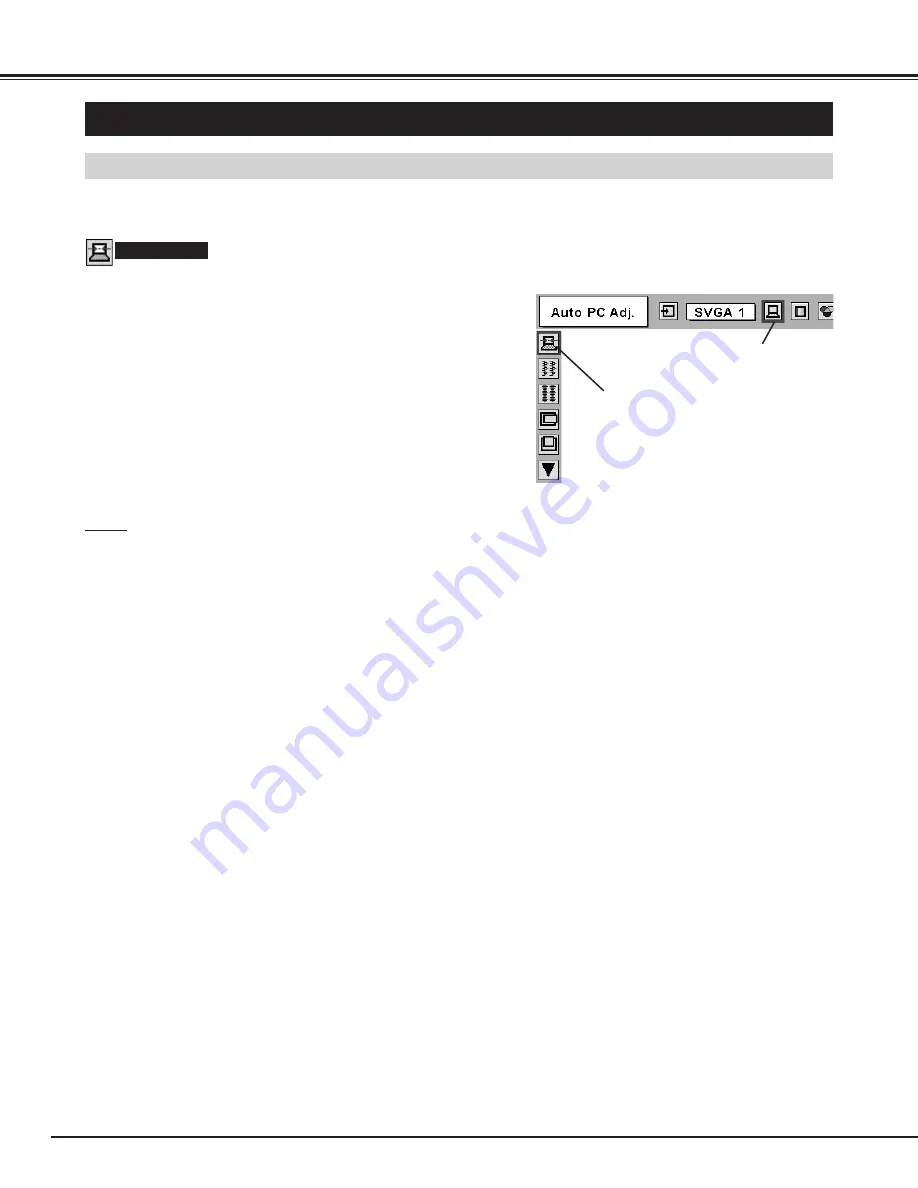
Press MENU button and ON-SCREEN MENU will appear.  Press
POINT LEFT/RIGHT button to move a red frame pointer to PC
ADJUST Menu icon.

1

2

Press POINT DOWN button to move a red frame pointer to
AUTO PC Adj. icon and then press SELECT button twice.
This Auto PC Adjustment can be also executed by pressing
AUTO PC ADJ. button on Top Control or on Remote Control
Unit.

Move a red frame pointer to AUTO PC
Adj. icon and press SELECT button.

PC ADJUST MENU

Auto PC Adj.

PC ADJUST Menu icon

Store adjustment parameters.
Adjustment parameters from Auto PC Adjustment can be memorized
in this projector.  Once parameters are memorized, setting can be
done just by selecting Mode in PC SYSTEM Menu (P26).  Refer to
step 3 of MANUAL PC ADJUSTMENT section (P30).

NOTE

Fine sync, Total dots and Picture Position of some computers can
not be fully adjusted with this Auto PC Adjustment function.  When
image is not provided properly through this function, manual
adjustments are required.  (Refer to page 29, 30.)

Auto PC Adjustment function cannot be operated in Digital Signal
input on DVI terminal and “RGB”,  “575p”,  “720p (HDTV)”,  “1035i
(HDTV)”, “1080i50 (HDTV)” or “1080i60 (HDTV)” is selected on PC
SYSTEM Menu (P26).

Содержание Matrix 2500 38-MX2001-01

Страница 1: ...User s Manual Projection lens is optional 38 MX2001 01 MODEL...

Страница 2: ...UCE THE RISK OF FIRE OR ELECTRIC SHOCK DO NOT EXPOSE THIS APPLIANCE TO RAIN OR MOISTURE This projector produces intense light from the projection lens Do not stare directly into the lens Eye damage co...

Страница 3: ...abinet slots as they may touch dangerous voltage points or short out parts that could result in a fire or electric shock Never spill liquid of any kind on the projector This projector should be operat...

Страница 4: ...with the limits for a Class A digital device pursuant to Part 15 of FCC Rules These limits are designed to provide reasonable protection against harmful interference when the equipment is operated in...

Страница 5: ...31 IMAGE LEVEL ADJUSTMENT 32 PICTURE SCREEN ADJUSTMENT 33 SELECTING INPUT SOURCE 34 SELECTING VIDEO SYSTEM 35 PICTURE IMAGE ADJUSTMENT 36 IMAGE LEVEL SELECT 36 IMAGE LEVEL ADJUSTMENT 37 PICTURE SCREE...

Страница 6: ...button is not pressed over 5 minutes Projection Lamp is automatically turned on again when a projector detects signal or any operation button is pressed This projector is shipped with this function ON...

Страница 7: ...ing power of Cooling Fans FRONT LAMP COVER This projector is equipped with cooling fans for protection from overheating Pay attention to following to ensure proper ventilation and avoid a possible ris...

Страница 8: ...ect a projector with a peripheral equipment before turning a projector on Refer to pages 12 15 for connection CONNECTING AC POWER CORD Connect AC Power Cord supplied to a projector AC outlet must be n...

Страница 9: ...to provide projected image where you want LENS SHIFT ADJUSTMENT MOVED UP OR DOWN Use LENS SHIFT button and POINT UP DOWN button to move image up or down Refer to page 22 This projector is designed to...

Страница 10: ...This may cause damage to a projector To transport a projector through a courier or transport service consult your dealer and best case should be applied Use carry handle when moving a projector Replac...

Страница 11: ...AUDIO OUT R L R R L L Screws Guide Socket Plug Figure shows HDB 15 PIN terminal Optional parts DVI Terminal 5 BNC Terminal 2 TERMINAL SLOTS Factory set Pull out terminal by holding handle Remove 2 Sc...

Страница 12: ...an audio output from computer or video equipment to these jacks Refer to P14 15 CONTROL PORT CONNECTORS AUDIO INPUT JACKS 5 BNC INPUT JACKS Connect component video output Cr Y Cb or Pr Y Pb from video...

Страница 13: ...to page 18 R C JACK USB PORT Series B R Pr G Y B Pb H HV V CONTROL PORT DVI INPUT 1 R C JACK USB RESET MONO MONO MONO AUDIO CONTROL PORT INPUT 2 INPUT 3 AUDIO SERIAL PORT IN SERIAL PORT OUT AUDIO OUT...

Страница 14: ...ADB port MAC VGA Adapter DVI VGA Adapter DVI Cable BNC Cable BNC x 5 Audio Cables RCA x 2 Control Cable for PS 2 Port Control Cable for ADB Port Audio Cable stereo NOTE When connecting cable power cor...

Страница 15: ...Audio Input Cables used for connection Video Cable BNC x 3 Audio Cable RCA x 2 Cables are not supplied with this projector NOTE When connecting cable power cords of both a projector and external equip...

Страница 16: ...of a projection lamp draws to an end P44 46 Flashes red when internal projector temperature is too high P42 Used to select input source P25 Used to select an item or adjust value in ON SCREEN MENU The...

Страница 17: ...Laser Light Window These caution labels are put on remote control LASER POINTER FUNCTION Used to select input source either INPUT 1 or INPUT 2 P25 Used to execute item selected or to expand or compres...

Страница 18: ...g Range Point Remote Control Unit toward projector Receiver Window whenever pressing any button Maximum operating range for Remote Control Unit is about 16 4 5m and 60 in front and rear of a projector...

Страница 19: ...perate each adjustment on ON SCREEN MENU 2 MOVING POINTER 3 SELECT ITEM Move pointer see below or adjust value of item by pressing POINT button s on Top Control or on Remote Control Unit Select item o...

Страница 20: ...o P35 IMAGE ADJUST MENU Used to adjust picture image Contrast Brightness Color Tint Color Temp White balance R G B Sharpness Gamma Noise Reduction Progressive Refer to P37 38 FOR VIDEO SOURCE Press ME...

Страница 21: ...ment function is ON projector detects signal interruption and turns off Projection Lamp automatically Refer to Power Management on pages 39 and 40 Press POWER ON OFF button again to turn off projector...

Страница 22: ...ect image with KEYSTONE adjustment ADJUSTING SCREEN Message disappears after 4 seconds Message disappears after 4 seconds Zoom Focus ZOOM ADJUSTMENT FOCUS ADJUSTMENT 1 Press ZOOM button on Top Control...

Страница 23: ...o black out a image To restore to normal press NO SHOW button again or press any other button except POINT SELECT RIGHT CLICK LASER button NO SHOW FUNCTION Message disappears after 4 seconds No show P...

Страница 24: ...t off sound Dialog box display is changed to On and sound is cut off To restore sound to its previous level press POINT LEFT RIGHT button s again Press POINT DOWN button to move a red frame pointer to...

Страница 25: ...Green Blue Horiz Sync and Vert Sync from a computer to R Pr G Y B Pb H HV and V jacks WHEN SELECT INPUT 2 5 BNC INPUT JACKS SELECTING COMPUTER SYSTEM WHEN SELECT INPUT 1 DVI INPUT TERMINAL Press MENU...

Страница 26: ...mputer Make sure connection of computer and a projector is set correctly Refer to TROUBLESHOOTING on page 47 Auto PC SYSTEM Menu icon Displays system being selected PC SYSTEM MENU SELECT COMPUTER SYST...

Страница 27: ...800 x 600 46 875 75 00 SVGA 4 800 x 600 53 674 85 06 SVGA 5 800 x 600 48 08 72 19 SVGA 6 800 x 600 37 90 61 03 SVGA 7 800 x 600 34 50 55 38 SVGA 8 800 x 600 38 00 60 51 SVGA 9 800 x 600 38 60 60 31 S...

Страница 28: ...t Move a red frame pointer to AUTO PC Adj icon and press SELECT button PC ADJUST MENU Auto PC Adj PC ADJUST Menu icon Store adjustment parameters Adjustment parameters from Auto PC Adjustment can be m...

Страница 29: ...ame pointer to PC ADJUST Menu icon 1 2 Press POINT DOWN button to move a red frame pointer to item that you want to adjust and then press SELECT button Adjustment dialog box will appear Press POINT LE...

Страница 30: ...a red arrow pointer to any of Mode 1 to 5 that you want to store and then press SELECT button Reset all adjust parameters on adjustment dialog box to previous figure Mode free Vacant Mode Shows values...

Страница 31: ...ENU Normal picture level preset on this projector Standard Picture level with improved halftone for graphics Real User preset picture adjustment in IMAGE ADJUST Menu P32 IMAGE 1 4 IMAGE SELECT Menu ic...

Страница 32: ...n Image Level Menu will appear Move a red frame pointer to Image 1 to 4 where you want to set and then press SELECT button Image Level Menu Move a red frame pointer to any of Image 1 to 4 where you wa...

Страница 33: ...V 1080i50 HDTV or 1080i60 HDTV is selected on PC SYSTEM Menu P26 Wide cannot be selected when 720p HDTV 1035i HDTV 1080i50 HDTV or 1080i60 HDTV is selected on PC SYSTEM Menu P26 This projector cannot...

Страница 34: ...o INPUT Menu icon Press POINT DOWN button and a red arrow icon will appear Move arrow to Y Pb Cb Pr Cr and then press SELECT button 1 3 When connect component video output Cr Y Cb or Pr Y Pb from vide...

Страница 35: ...atically detects incoming Video signal and adjusts itself to optimize its performance When Video System is 1035i 1080i50 or 1080i60 select system manually first If projector can not reproduce proper v...

Страница 36: ...Normal picture level preset on this projector Standard Picture level adjusted for picture with fine tone Cinema User preset picture adjustment in IMAGE ADJUST Menu P38 IMAGE 1 4 IMAGE SELECT Menu icon...

Страница 37: ...From 0 to 15 Sharpness Press POINT LEFT button to lighten red tone and POINT RIGHT button to deeper tone From 0 to 63 White balance Red Press POINT LEFT button to lighten green tone and POINT RIGHT bu...

Страница 38: ...0i50 or 1080i60 is selected on AV SYSTEM Menu P35 Move a red frame to function and press SELECT button SCREEN MENU SCREEN Menu icon Provides image at a wide screen ratio of 16 9 Wide Provides image at...

Страница 39: ...is selectable from among English German French Italian Spanish Portuguese Dutch Swedish Russian Chinese Korean and Japanese Display This function decides whether to display On Screen Displays On show...

Страница 40: ...mote control This projector has two different remote control codes factory set normal code Code 1 and secondary code Code 2 This switching function prevents remote control operation mixture jam when o...

Страница 41: ...icator stops lighting Turn projector on press MENU button and ON SCREEN MENU will appear Press POINT LEFT RIGHT button s to move a red frame pointer to SETTING Menu icon 1 Press POINT DOWN button to m...

Страница 42: ...CLICK button on Wireless Remote Control Unit Used to move PC mouse pointer Pointer is moved corresponding with direction you are pressing POINT button This button has same function as left button in a...

Страница 43: ...When using under dusty or smoky conditions dust may accumulate on liquid crystal panel lens or optical elements inside it This condition may degrade quality of projected image When above symptoms are...

Страница 44: ...flashes when any of them becomes out Check number of lamp on Lamp Status Display and replace lamp Yellow Lamp Dim Lamp X Mark on Lamp Red Lamp LAMP REPLACE INDICATOR Projection Lamp is turned off Pro...

Страница 45: ...RATE A PROJECTOR WHILE ANY OF LAMPS IS REMOVED IT MAY RESULT IN MALFUNCTIONS FIRE HAZARD OR OTHER ACCIDENTS SCREWS LAMP COVER SCREWS Make sure which number of lamp needs to be replaced on Lamp Status...

Страница 46: ...he environment or conditions in which the projector and lamp are being used IF A LAMP EXPLODES THE FOLLOWING SAFETY PRECAUTIONS SHOULD BE TAKEN If a lamp explodes disconnect the projector s AC plug fr...

Страница 47: ...After pressing Power ON OFF button to OFF make sure a projector works as follows 1 LAMP indicator lights bright and READY indicator turns off 2 After 90 seconds READY indicator lights green again and...

Страница 48: ...xplain difficulty We will advise you how to obtain service This symbol on the nameplate means the product is Listed by Underwriters Laboratories Inc It is designed and manufactured to meet rigid U L s...

Страница 49: ...Feet Adjustment Power Source AA UM3 or R06 Type x 2 Operating Range 16 4 5m 30 Dimensions 2 2 x 1 3 x 7 6 55mm x 34mm x 192mm Net Weight 0 36 lbs 165 g including batteries Laser Pointer Class II Lase...

Страница 50: ...15 23 8 16 24 C1 C2 C3 C5 C4 T M D S Data2 No Connect T M D S Data2 No Connect T M D S Data2 Shield DDC Clock DDC Data Analog Vert sync 1 5 2 4 3 6 7 8 Pin Configuration T M D S Data1 No Connect T M...

Страница 51: ...APPENDIX Vcc Data Data Ground 1 2 3 4 USB PORT TERMINAL Pin Configuration Connect USB port output terminal of computer or peripheral equipment to this terminal with USB port Cable not supplied 2 3 4...

Страница 52: ...Printed in Japan Part No 10 A 610 307 2654 1AA6P1P4033 ME7KW...

Отзывы: