Chore-Time C2 PLUS Скачать руководство пользователя страница 45

MODEL C2® Plus & MODEL G™ Plus Feeding System

Parts Listing

MF1255C

45

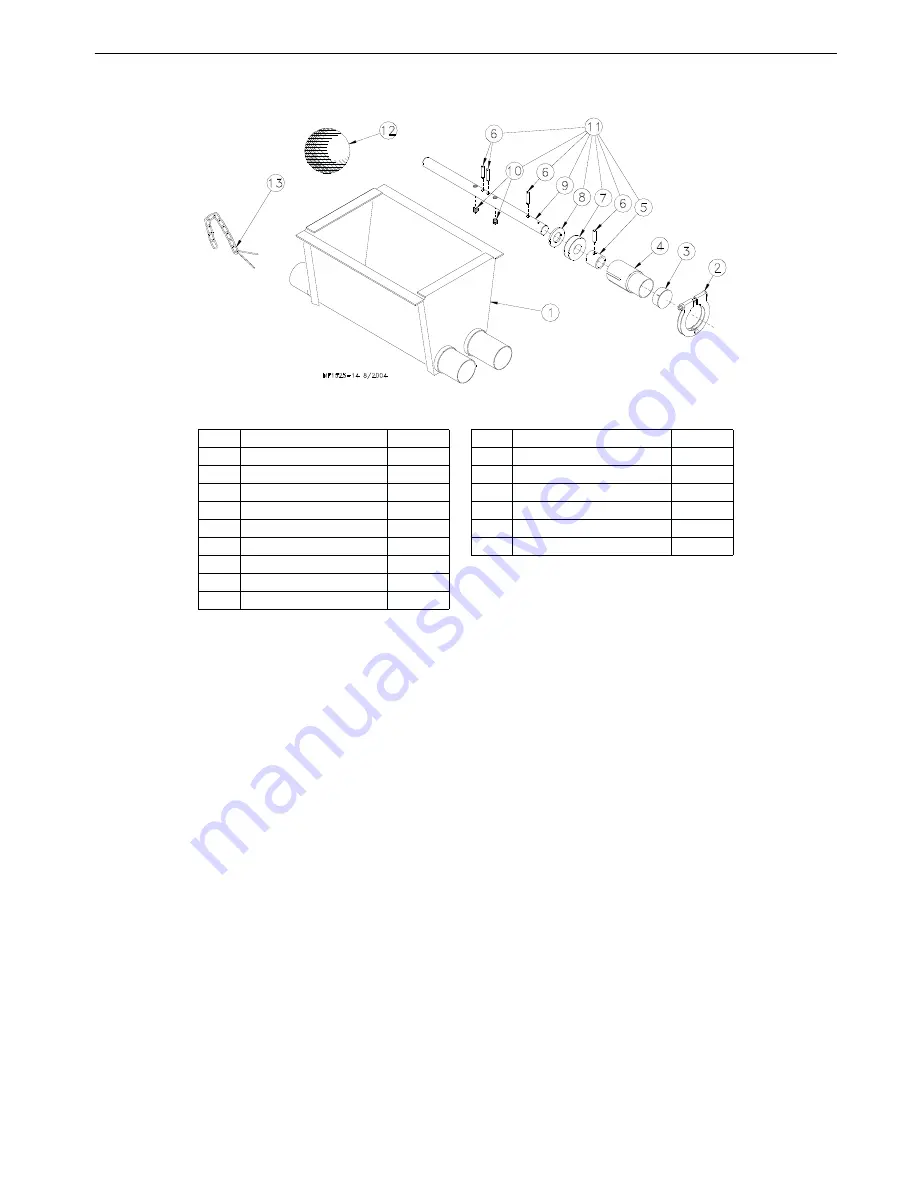
Twin Boot Components Part No. 6824

*The Jumper Wire Kit includes an insulated piece of High-Voltage Wire (part no. 28994) and (2) cable clamps.

Item Description

Part No.

Item Description

Part No.

1

Boot Weldment

3932

10

Setscrew

47867

2

Tube Clamp

24063

11

Anchor and Bearing Ass’y

39372

3

Cap

29373

12

Cannonball

3531

4

Outlet Tube

4556

13

Latch Pin Ass’y

2683

5

Sleeve

5648

--*

Jumper Wire Kit

5960

6

3/16 x 1" Pin

2960-1

--

Danger Decal

2527-9

7

Bearing

2689

8

Washer

2955-14

9

Anchor

38540

Содержание C2 PLUS

Страница 1: ...MODEL C2 Plus MODEL G Plus Feeding System Installation and Operators Manual 1255 111 10 2000 MF1255C August 2004 ...

Страница 2: ...ty period shall apply 1 TURBO and RLX fans less motors 3 years 2 TURBO fan fiberglass housings polyethylene cones and cast aluminum blades for the life of the product 3 TURBO fan motors and bearings 2 years 4 TURBO fan components including plastic shutters 3 years 5 Poultry feeder pans that becomes unusable within five years from the date of installation Warranty prorated after three years usage 6...

Страница 3: ...RER S ENTIRE AND SOLE WARRANTY AND THIS MANUFACTURER EXPRESSLEY DISCLAIMS ANY AND ALL OTHER WARRANTIES INCLUDING BUT NOT LIMITED TO EXPRESS AND IMPLIED WARRANTIES AS TO MERCHANTIBILITY FITNESS FOR PARTICULAR PURPOSES SOLD AND DESCRIPTION OR QUALITY OF THE PRODUCT FURNISHED HEREUNDER Chore Time Distributors are not authorized to modify or extend the terms and conditions of this Warranty in any mann...

Страница 4: ...nch Cable 12 Screw Hook Installation 13 Ceiling Hook Installation 14 Drop Installation 15 Feeder Pan Assembly 16 Feeder Line Assembly and Suspension 16 Feeder Pan and Tube Assembly Process 16 Assemble and Suspend the Feeder Line 17 Installing the End Control Boot Assembly and Auger 19 Auger Installation 19 Auger Brazing 24 Anti Roost Installation 25 Mid Line Control 28 Feeder Management and Operat...

Страница 5: ...itch Three Phase Ø Wiring Diagram 220 V 41 Mechanical Switch Three Phase Ø Wiring Diagram 380 415 V 41 Parts Listing 42 200 Hopper Components 42 100 Hopper Components 43 Hopper Mount Bracket Optional 44 Single Boot Components Part No 6822 45 Twin Boot Components Part No 6824 45 Feeder Line Components 46 Model C2 Plus Feeder Pan Assemblies 47 Model C2 Plus Shallow Feeder Pan Assemblies 48 Model G P...

Страница 6: ...t number Caution Warning and Danger Decals have been placed on the equipment to warn of potentially dangerous situations Care should be taken to keep this information intact and easy to read at all times Replace missing or damaged safety decals immediately Using the equipment for purposes other than specified in this manual may cause personal injury and or damage to the equipment Safety Alert Symb...

Страница 7: ... electrical wiring must be done by a qualified electrician in accordance with local and national electric codes Ground all non current carrying metal parts to guard against electrical shock With the exception of motor overload protection electrical disconnects and over current protection are not supplied with the equipment CAUTION Use caution when working with the Auger springing Auger may cause p...

Страница 8: ...ype Max weight and or weeks of age Feeders Number of birds pan Broiler 4 5lbs 2kg Revolution 12 Models C2 Plus C2Plus S C H2 H2 Plus 60 90 Broiler 7lbs 3 1kg Revolution 8 C2 Plus C2 Plus S G Plus G Plus S C H2 H2 Plus 55 75 Broiler 9lbs 4 0kg Revolution 8 G Plus G Plus S 45 65 Broiler Breeder Pullet rearing 0 18 weeks C2 Plus Breeder C2 Plus S Breeder 14 15 Broiler Breeder Pullet rearing 0 18 week...

Страница 9: ...Determine the Brood Curtain location 4 Determine the location for the End Control Pans and if used the Mid Line Control Pans The Feeder Control Pans should be at least 10 3 m from the Wall or Brood Curtain 5 Determine the distance to the Feeder Line from the Side Wall 6 Determine the distance from the Feed Hoppers to the End Wall for a Straight Line Feeding System Planning the Floor Feeding System...

Страница 10: ...nt The Model C2 Plus and G Plus Control Units use a 348 RPM Gearhead delivering approximately 17 lbs 7 7 kg per minute This rating is based on feed with a density of 40 lbs per cubic foot 640 kg per cubic meter Single phase 60 Hz and single and three phase 50 Hz Power Units are available for the Model C2 Plus G Plus Feeders Systems up to 300 91 m require 1 3 HP Power Units Systems over 300 91 m re...

Страница 11: ...r Lift Winch Support either a 2 x 8 50x200 mm board that will span at least 3 rafters or a 3 8 9 5 mm thick steel plate welded to two pieces angle iron that are each long enough to span at least 2 rafters using 5 16 18 hardware supplied in the Hardware Package The brake mechanism will extend toward one side Install a Cable Hook supplied in Hardware Package between the mounting bolt and Power Winch...

Страница 12: ...cations The Feeder Line must be supported within 3 9 m of the Power Unit This is in addition to the required Power Unit suspension If the Control Unit or Hopper does not come out directly under a truss fasten a pulley to a 2 x 8 50 x 200 mm board or steel angle that will span 2 trusses and is capable of supporting 300 lbs 136 kg for the Hopper and 75 lbs 34 kg for the Control Unit Feed Hopper Loca...

Страница 13: ... each side of the line to prevent the cable clamps from catching the pulleys See Figure 12 Screw the hook into the truss the full length of the threads to prevent bending The openings of the screw hooks must be pointed away from the direction of travel when the Power Winch raises the feeder line See Figure 13 1255 80 1 2001 1 Winch Drum Relief with Set Screw 2 3 16 Main Winch Cable 3 Drum Directio...

Страница 14: ...s Wood Truss Installations 1255 74 9 2000 1 Secure Ceiling Hook to truss using self drilling screws through opposite holes 2 Cable Travel Figure 14 Steel Truss Ceiling Bracket Installation 1255 76 9 2000 2 Cable Travel 1 Weld Ceiling Bracket to truss here 1 Weld Ceiling Bracket to truss here Figure 15 Welded Steel Truss Ceiling Bracket Installation 1255 77 3 2001 1 Secure Ceiling Bracket to truss ...

Страница 15: ...le clamp See applicable figure Figure 13 or 17 3 Allow enough cable length for installation of the Adjustment Leveler Sufficient cable is included to provide throwbacks on drops located beneath and near the winch Figure 18 shows a throwback cable arrangement 4 Begin installing suspension drops at the winch and proceed to the ends of the feeder line Keep the main cable tight between drops It may be...

Страница 16: ...ubes IMPORTANT Install all the feeders on the tubes in the same orientation When sliding the feeders on the tubes make sure the grill openings are on the same side of the tube 1 Rotate the auger tubes so that the seam is down this holds the Pan Assemblies in place on the tubes See Figure 20 Figure 20 Assemble Feeders on tubes Feeder Pan Assembly Feeder Line Assembly and Suspension Rotate the Feede...

Страница 17: ...n of the tubes and all the Hangers should be installed as shown in Figure 22 4 Place a Tube Clamp Assembly or Clamp Anti Roost Bracket at each joint Figure 23 shows the standard Clamp and Clamp Anti Roost Bracket Systems using 9 or 10 tubes require a Clamp Anti Roost Bracket at every fifth joint Systems using 12 tubes require a Clamp Anti Roost Bracket at every fourth joint All other joints in the...

Страница 18: ...erly on all pulleys before raising the feeder line 8 Raise the feeder line to a convenient working height 9 With the feeder line suspended measure from the floor or ceiling to the auger tubes to level the system 10 Before tightening each clamp make sure each tube is level not sagging sloping etc make sure straight end of each tube is fully inserted in belled end of next tube if providing total dro...

Страница 19: ...extreme caution when working with the auger The auger is under tension and may spring causing personal injury Wear protective clothing gloves and safety glasses when working with the auger To avoid kinking the auger be careful not to drop the rolled auger when handling Inspect the auger carefully as it is installed Small kinks may be straightened Large kinks must be removed and the auger brazed ba...

Страница 20: ... boot uncoil the auger from the outside and feed the auger through the boot into the tubes Push the auger into the tube in short strokes Uncoil and handle the auger carefully to avoid damaging or kinking the auger 2 If more that one coil is required for each feeder line the auger ends will have to be brazed together Refer to the Brazing the Auger section in this manual 3 Install the Anchor Bracket...

Страница 21: ... 30 Use the Driver Block to secure the auger to the Output Shaft 7 Attach the Anchor Plate and Gearhead Assembly to the Control Unit Body using the included 1 4 Lock Washers and 1 4 20 x 1 2 Bolts See Figure 31 1255 93 4 2001 2 Drive Tube Weldment 1 Driver Block 3 Control Unit not shown for clarity 4 1 4 20 x 1 1 2 Socket Head Bolt 6 Auger Figure 30 Auger Driver Components Anchor Plate and Gearhea...

Страница 22: ...e Figure 33 Figure 33 Measure the Auger from the relaxed position 11 Auger stretch The auger needs to be stretched 7 180 mm per 100 30 m Example A 300 90 m feeder line requires 21 500 mm of stretch Beginning at the relaxed position measure the required amount of stretch Mark the auger at that point Grip the auger 8 200 mm ahead of this mark with locking pliers Allow the auger to pull back into the...

Страница 23: ...ully remove the locking pliers while holding onto the Anchor and Bearing Assembly and auger securely Slowly ease the auger back into the tube Use caution If the auger is allowed to spring back the bearing race may crack Install the Bearing Retainer and fasten with a tube clamp Keep the Bearing Retainer flush with the end of the anchor for safety 14 Place the cannonball in the boot 1255 95 9 2000 1...

Страница 24: ...INSIDE EACH OTHER See Figure 36 The joint should be well filled with no sharp edges or rough corners to wear against the tube To align the auger for brazing lay it in angle or channel iron and clamp it firmly in place Use low heat Allow the joint to air cool rapid cooling will cause the auger to become brittle Figure 36 Auger Brazing 1255 97 9 2000 1 Braze here 1 Braze here 2 Lap the auger ends ap...

Страница 25: ...ng Pull the cable tight so that there is 3 4 to 1 20 to 25 mm of stretch in the spring Clamp the cable to form a loop and cut off any excess See Figure 39 6 Attach the cable to the insulator For best results make a double loop around the anti roost insulator in the center groove of the insulator and fasten with a 1 16 cable clamp as shown in Figure 39 7 Run the cable to the next insulator attach a...

Страница 26: ...re 40 Anti Roost Installation at the Control Unit 11 Install the Poultry Trainer or Line Charger as shown in Figure 41 or 42 The Poultry Trainer is used to power all Anti Roost lines in a house See Figure 41 The Line Charger is used to power individual Anti Roost lines in a house See Figure 42 Route the charger wire from the Poultry Trainer or Line Charger to the Anti Roost system Secure the Charg...

Страница 27: ...e Charger Installation 12 The anti roost system must be on a separate electrical circuit allowing the system to be disconnected by a switch near the door Remember the anti roost system should be grounded through the poultry trainer 1255 92 9 2000 1 Line Charger 2 Insulated Charger Wire 3 Anti Roost Wire ...

Страница 28: ...his control box until electrical power is disconnected at circuit breakers ELECTROCUTION HAZARD DANGER 1255 98 9 2000 2529 712 42664 MODEL G PLUS INTERMEDIATE CONTROL WITH PROXIMITY SWITCH CHORE TIME EQUIPMENT A DIVISION OF CTB INC MILFORD INDIANA 46542 2000 Do not open this control box until electrical power is disconnected at circuit breakers ELECTROCUTION HAZARD DANGER Model C2 Plus Mid Line Co...

Страница 29: ...r Lines Enlarge the outlet hole to approximately 1 2 5 cm diameter for the Mid Line Control plus enlarge 2 outlet holes in front to the hopper end of the Mid Line Control Use unibit to enlarge hole size Be sure there are no burrs inside the tube to catch the auger 3 Install the Mid Line Control Mechanical Switch a Remove the two hex head screws on the control top b Lift off the control top c Cradl...

Страница 30: ... to the Mid Line Control This allows the Mid Line Control to serve as standard feeder when not used as a control feeder 5 Wire the Mid Line Control as shown in the wiring diagram section of this manual 1255 66 6 01 2529 711 42663 MODEL C2 PLUS INTERMEDIATE CONTROL WITH PROXIMITY SWITCH CHORE TIME EQUIPMENT A DIVISION OF CTB INC MILFORD INDIANA 46542 2000 Do not open this control box until electric...

Страница 31: ...one end and the control pan power unit at the other end See Figure 49 It is common practice to use partial house brooding during the early days of broiler production For buildings that have the feeder split in the center center hopper set up normally only the feeders that are in the brood area are used during brood time For buildings that have the hopper at one end brooding can be done on the moto...

Страница 32: ...s are used General Operation of the MODEL C2 PLUS and MODEL G PLUS Feeders These recommendations are the guideline to aid producers with the use of the feeding system With experience a feeding program will be developed to enhance the feeding systems performance Several factors such as feed content type of birds climate lighting programs and etc may dictate change from these recommendations The Mod...

Страница 33: ...nd of the feeder line It is important the feed setting of the end control pan be the same as the rest of the feeder pans so the birds activate the feeder see page 34 for adjustment of the control The Mid Line Control is placed on the feeder line when partial house brooding is desired It is important the mid line control be installed at least 2 feeder pans away from the curtain or partition so the ...

Страница 34: ...ne remove the thinned area from the Non Windowed Feed Cone then insert the Slide Shut Off into the slots as shown in Figure 52 Figure 52 Optional Slide Shut Off Assembly An Optional Pan Extension is available for MODEL G Plus Feeder Pan Assemblies The Pan Extension is used for Turkey Hens To assemble the Pan Extension on the MODEL G Plus Feeder Pan Assembly place the Pan Extension around the MODEL...

Страница 35: ...s B Wipe any debris off the magnet on the bottom Pipe Plug and reinstall Remove the side Pipe Plug and top Vent Plug C Set the power unit in the horizontal position D 2 Stage Gearheads Add approximately 9 oz 266 ml of SAE 40W oil through top hole This should be just enough oil to reach the side Pipe Plug 3 Stage Gearheads 3261 9 3261 12 3261 14 Add approximately 13 oz 384 ml of SAE 40W oil through...

Страница 36: ...t Screw counter clockwise Light blinks fast For more time turn Time Delay Adjustment Screw clockwise Light blinks slow Figure 56 Adjusting the SENSOR PLUS Proximity Switch Feeder Line Keep anti roost cables tightly stretched This increases the effectiveness of the electro guard anti roost system and keep the pans from being tilted when birds push against them Remove all feed from the feeder when t...

Страница 37: ...he auger hits the flat washer Tighten the setscrews in the center of the anchor until they touch the See Figure 57 2 Carefully remove the locking pliers while holding onto the Anchor and Bearing Assembly and auger securely Slowly ease the auger back into the tube Use caution If the auger is allowed to spring back the bearing race may crack Install the Bearing Retainer and fasten with a tube clamp ...

Страница 38: ...oads frequently Oil on new auger loads motor excessively when feed is carried for first time Polish auger by running 50 lb 20 kg increments of feed out to pans Inadequate power reaching motors Check line voltage at the motors Check starting current draw at motors Wiring of adequate size is essential to feeder operation Object caught in the auger motor runs stalls then auger spins in reverse Check ...

Страница 39: ...CHORE TIM E EQUIPM EN T A DIVISION OF CTB INC MILFO RD INDIANA 46542 2000 Do not open this control box until electrical po wer is disconn ected at circu it breakers ELECTROCUTION HAZARD DANGER 25 29 711 42663 MODEL C2 PLUS INTERMEDIATE CONTROL WITH PROXIMITY SWITCH C HORE TIM E EQUIPM EN T A DIV ISION OF CTB IN C MILFORD INDIA NA 46542 2000 Do no t op en this control bo x un til electrical power i...

Страница 40: ...30 VOLTS 50 60 HZ FEEDER LINE MOTOR 220 230 VOLTS 50 60 HZ SINGLE PHASE TOGGLE SWITCH SPST 15 AMP NOT SUPPLIED MID LINE CONTROL UNIT 95 END CONTROL 96 1255 108 10 2000 K1 L2 T2 L3 T3 SINGLE PHASE C1 K1 CONTACTOR L1 T1 FROM DISCONNECT OR CONTROL DISCONNECT 220 230 VOLTS 50 60 HZ TO ADDITIONAL FEEDER LINES MID LINE CONTROL UNIT CONTROL BYPASS SWITCH NOT SUPPLIED SET OF FUSES SHORT CIRCUIT PROTECTION...

Страница 41: ...SES SHORT CIRCUIT PROTECTION NOT SUPPLIED CURRENT SENSOR AVAILABLE FEEDER LINE MOTOR 220 230 VOLTS 50 HZ THREE PHASE MID LINE CONTROL UNIT CONTROL BYPASS SWITCH NOT SUPPLIED M1 3 PH C1 END CONTROL 96 1255 110 10 2000 95 K1 PHASE PHASE PHASE NEUTRAL L2 L3 T2 T3 C1 L1 CONTACTOR CURRENT SENSOR AVAILABLE K1 T1 FROM DISCONNECT OR CONTROL DISCONNECT 380 415 VOLTS 50 HZ THREE PHASE TO ADDITIONAL FEEDER L...

Страница 42: ...r Assembly may be ordered under Part No 7941 Hopper Cover must be ordered separately Parts Listing Item Description Part No 1 Hopper Cover optional 28206 2 Tube Support Assembly 14367 3 Hopper Side 2680 4 Boot Hanger 2671 5 Hanger Bracket Assembly 2681 6 Adjustment Bracket 2706 7 Hair Pin 2664 8 Clevis Pin 5 16 x 1 2797 1 1660 02 10 2000 1 8 5 6 7 3 2 4 3 ...

Страница 43: ...o 28220 The 100 Hopper Assembly including the Cover may be ordered under Part No 28240 Key Description Part No 1 Hopper Cover w o hole 28211 2 Hopper Cover w hole 28212 3 Hopper Hanger 28165 4 Adjustment Bracket 2706 5 Clevis Pin 5 16 x 1 2797 1 6 Hair Pin 2664 7 H L C Mounting Bracket 28267 8 Hopper Side w hole 24241 9 Boot Hanger 28168 10 Tube Support Assembly 14367 1660 01 10 2000 1 2 3 4 5 6 7...

Страница 44: ...1 2 Adjustment Bracket 2706 2706 3 Hair Pin 2664 2664 4 Suspension Brace 48680 48680 5 Suspension Angle 48679 48679 6 Cable Guide 34573 34573 Item Description Part No Item Description Part No 1 Boot Weldment 3760 9 Anchor 38540 2 Tube Clamp 24063 10 Setscrew 47867 3 Cap 29373 11 Anchor and Bearing Ass y 39372 4 Outlet Tube 4556 12 Cannonball 3531 5 Sleeve 5648 13 Latch Pin Ass y 2683 6 3 16 x 1 Pi...

Страница 45: ...part no 28994 and 2 cable clamps Item Description Part No Item Description Part No 1 Boot Weldment 3932 10 Setscrew 47867 2 Tube Clamp 24063 11 Anchor and Bearing Ass y 39372 3 Cap 29373 12 Cannonball 3531 4 Outlet Tube 4556 13 Latch Pin Ass y 2683 5 Sleeve 5648 Jumper Wire Kit 5960 6 3 16 x 1 Pin 2960 1 Danger Decal 2527 9 7 Bearing 2689 8 Washer 2955 14 9 Anchor 38540 ...

Страница 46: ...12 4 Hole Tube 12 5 Hole Tube 6854 1 6854 5 6854 4 6854 8 6854 7 6854 6 12 Standard Feeder Tube 1 3 4 with Chick Holes EZ Holes 9 4 Hole 4 EZ Holes 10 4 Hole 4 EZ Holes 12 4 Hole 4 EZ Holes 12 5 Hole 5 EZ Holes 10 3 Hole 3 EZ Holes 9 4 Hole 2 EZ Holes 10 4 Hole 2 EZ Holes 12 4 Hole 2 EZ Holes 6854 15 6854 16 6854 17 6854 18 6854 19 6854 20 6854 21 6854 22 13 Control Feeder Tube 1 3 4 Roll Form 9 4...

Страница 47: ...eeder Assembly Non Window and Removable Top 42697 Model C2 Plus Feeder Assembly with Shut Off 42700 Model C2 Plus Feeder Assembly with Removable Top and Shut Off 42695 Model C2 Plus Feeder Assembly Non Window and Shut Off 42698 Model C2 Plus Feeder Assembly Non Window and Removable Top and Shut Off 39567 38604 38601 38602 39566 39565 38603 42701 42703 42705 42706 39564 X X X X X X X X X X X X X X ...

Страница 48: ...2009 Model C2 Plus Shallow Feeder Non Window and Removable Top 43470 Model C2 Plus Shallow Feeder with Shut Off 43472 Model C2 Plus Shallow Feeder with Removable Top and Shut Off 42696 Model C2 Plus Shallow Feeder Non Window and Shut Off 42699 Model C2 Plus Shallow Feeder Non Window and Removable Top and Shut Off 39567 41504 41502 41503 41505 41892 38603 42237 42238 42678 42677 39564 X X X X X X X...

Страница 49: ...eder Assembly Non Window and Removable Top 42694 Model G Plus Feeder Assembly with Shut Off 42691 Model G Plus Feeder Assembly with Removable Top and Shut Off 42692 Model G Plus Feeder Assembly Non Window and Shut Off 42689 Model G Plus Feeder Assembly Non Window and Removable Top and Shut Off 38599 38604 38601 38602 39566 39565 38603 42701 42703 42705 42706 39564 X X X X X X X X X X X X X X X X X...

Страница 50: ...2025 Model G Plus Shallow Feeder Non Window and Removable Top 42707 Model G Plus Shallow Feeder with Shut Off 42708 Model G Plus Shallow Feeder with Removable Top and Shut Off 42693 Model G Plus Shallow Feeder Non Window and Shut Off 42690 Model G Plus Shallow Feeder Non Window and Removable Top and Shut Off 38599 41504 41502 41503 41505 41892 38603 42237 42238 42678 42677 39564 X X X X X X X X X ...

Страница 51: ... 5083 8 5083 8 5083 8 9 Vent Plug 3516 3516 3516 3516 3516 3516 3516 10 Flat Washer 1484 1484 1484 1484 1484 1484 1484 11 S Hook 2805 2805 2805 2805 2805 2805 2805 Cord Assembly 4685 8299 28028 Connector Romex 1317 1317 Connector 90 Degree 4228 Part No HP RPM Phase Hz Voltage Usages 3259 8 1 3 HP 348 RPM Single Phase 60 Hz 230 Use with 1878 8 Control Unit ONLY 3259 25 1 2 HP 348 RPM Single Phase 6...

Страница 52: ...0943 MODEL C2 PLUS CHORE TIME EQUIPMENT A DIVISION OF CTB INC MILFORD INDIANA 46542 2000 DANGER Do not open this control box until electrical power is disconnected at circuit breakers CONTACT RATINGS 1 2 H P 115 VAC 1 H P 230 VAC WITH WINDOW 25 24 23 22 21 29 28 27 26 36 37 35 30 34 31 33 32 3 1 2 4 5 8 10 11 12 13 14 15 17 16 6 7 9 30 31 20 18 19 ...

Страница 53: ...Bracket 46122 46122 46122 46122 14 Switch Insulation 1907 5 1907 5 1907 5 1907 5 15 Actuator Switch 46091 46091 46091 46091 16 1 2 Liquid Tight Connector 23810 23810 23810 23810 17 14 Flexible Conduit 26982 1 26982 1 26982 1 26982 1 18 Straight Liquid Tight Connector 26980 26980 26980 26980 19 Cut Sleeve 43110 43110 43110 43110 20 Anchor Plate 4188 4188 4188 4188 21 Center Support Assembly 40947 3...

Страница 54: ...8 INTERMEDIATE CONTROL 40945 MODEL C2 PLUS CHORE TIME EQUIPMENT A DIVISION OF CTB INC MILFORD INDIANA 46542 2000 DANGER Do not open this control box until electrical power is disconnected at circuit breakers CONTACT RATINGS 1 2 H P 115 VAC 1 H P 230 VAC WITH WINDOW 13 2 3 8 9 10 11 12 5 4 7 6 16 17 19 18 20 21 23 24 15 14 27 26 25 10 22 1 ...

Страница 55: ... 25048 25048 25048 25048 8 Spring 6972 6972 6972 6972 9 10 32 Lock Nut 6963 6963 6963 6963 10 Gasket 6968 1 6968 1 6968 1 6968 1 11 Switch Box Cover 6776 6776 6776 6776 12 Gasket 6777 6777 6777 6777 13 Actuator Pin 8757 8757 8757 8757 14 Support Cone Assembly 40947 37371 40947 37371 15 Tube Retainer 14756 14756 14756 14756 16 Cord Assembly 4999 49 4999 49 4999 49 4999 49 17 1 2 Liquid Tight Connec...

Страница 56: ...Parts Listing MODEL C2 Plus MODEL G Plus Feeding System 56 MF1255C SENSOR PLUS End Control SAME COVER FRONT AND BACK 25 20 13 9 14 15 11 10 8 7 6 5 4 3 2 1 19 18 17 24 25 23 26 27 28 22 21 ...

Страница 57: ...t Connector 26980 26980 26980 26980 11 Switch Box Gasket 6777 6777 6777 6777 12 13 Danger Product Identification Decal 2529 710 2529 731 2529 709 2529 729 14 Cord Assembly 4999 100 4999 100 4999 100 4999 100 15 Liquid Tight Connector 24685 24685 24685 24685 16 17 Grill 39567 39567 38599 38599 18 Adjustment Cone 38604 41504 38604 41504 19 Feeder Pan 41501 41500 41501 41500 20 10 x 1 2 Hex Washer He...

Страница 58: ...38603 38603 38603 7 Hose Clamp 3527 3527 3527 3527 8 10 x 1 2 Hex Washer Head Screw 28075 28075 28075 28075 9 Switch Box Gasket 6777 6777 6777 6777 10 11 Liquid Tight Connector 23779 23779 23779 23779 12 Tube Mount 42681 42681 42681 42681 13 Terminal Box Mounting Cover 6956 6956 6956 6956 14 Liquid Tight Connector 24685 24685 24685 24685 15 General Purpose Terminal Box 42627 2 42627 2 42627 2 4262...

Страница 59: ...19 Retaining Ring 3556 6 5 16 Flat Washer 2255 44 20 Washer 2955 2 7 Spring 1543 21 Winch Drum 3723 8 Spring Washer 4023 22 Drum Shaft 3637 9 Intermediate Gear 2890 23 Setscrew 603 10 Flange Bushing 3252 24 Winch Frame 3719 11 Spirol Pin 2960 3 25 Setscrew 3727 12 Bushing 2967 4 26 Cable Hook 2985 13 Washer 2955 1 27 Grease Zerk 24499 14 Retaining Ring 2958 1 28 Washer 2499 1255 54 4 1998 1 2 3 It...

Страница 60: ...l 3004 4 Heavy Duty Pulley Assembly 2014 5 Pulley 2500 6 3 16 Cable Clamp 732 7 ATF Screw Hook 2041 8 Extendable drive tube 47637 9 Pulley Assembly 28429 10 Ceiling Hook 28550 11 Handle Shank 3148 12 Drill Adapter Shaft 2886 13 Winch Handle Pin 3761 14 Winch Drive Tube 4 2884 1 Winch Drive Tube 8 2884 2 Winch Drive Tube 2 2884 4 Full Line Suspension Kit 7948 Item 11 and Item 13 may be ordered as a...

Страница 61: ...MODEL C2 Plus MODEL G Plus Feeding System Parts Listing MF1255C 61 This page intentionally left blank ...

Страница 62: ...arby Chore Time distributor or representative for additional parts and information CTB Inc P O Box 2000 Milford Indiana 46542 2000 U S A Phone 574 658 4101 Fax 877 730 8825 E Mail poultry choretime com Internet http www choretime com Printed in the U S A ...

Отзывы: