background image

TROUBLE SHOOTING

14

10H52164PUMC     REV. 1/11-2003

UK

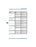
Possible  Cause

Symptom

No Led display
on the front
panel.

Alarm buzzer beeps
continuously when AC
supply is normal.

When power failure,
back-up time is shorten.

Communication lost
between UPS and
computer.

Mains normal but green
LEDs are on.

1)  Charge battery up to

8 hours.

2)  Replace with the same

type of battery.

3)  Press power switch for

at least 5 seconds.

Verify that the load
matches the UPS
capability specified in
the specs.

1) Remove some

noncritical load.

2)  Charge battery 8 hours

or more.

3)  Replace with the same

type of battery.

1)  Check the setting of

the software.

2)  Check the RS-232

cable is firmly connected
to COM1/COM2 of the
computer and confirm
the setting again.

1)  Replace the same
     type of fuse.

2)  Reconnect the power
     cord properly.

Remedy

1) Missing battery.

2) Battery defect.

3)  Power switch is not

pressed at least 5 second.

Overload of the UPS.

1)  Overload of the UPS.

2)  Battery voltage is too low.

3)  Battery defect due to high

temperature operation
environment, to battery.

1)  Software is not

installed well.

2)  Cable is not properly
     connected.

1)  Fuse is blown.

2)  Power cord is loose.

Содержание Desk Power Plus 1000

Страница 1: ...on only and is not deemed to form any part of any offer and contract The company has a policy of continuous product development and improvement and we therefore reserve the right to vary any information without prior notice Cert No FM 10144 CHLORIDE POWER PROTECTION 10H52164PUMC ...

Страница 2: ...Desk Power Plus Operating Manual CHLORIDE POWER PROTECTION ...

Страница 3: ......

Страница 4: ......

Страница 5: ...ungsfreie Stromversorgung Benutzer Handbuch 17 E Sistema de Alimentación Ininterrumpida Manual de usuario 29 F Alimentation Sans Interruption Manuel Utilisateur 41 I Gruppo di continuità Manuale d uso 53 P Sistema de Alimentação Ininterrupta Manual do Utilizator 65 ...

Страница 6: ...4 10H52164PUMC REV 1 11 2003 ...

Страница 7: ...TION AND OPERATION 3 Inspection 10 4 Placement 10 5 Charging 11 6 Computer Connection 11 7 Modem Phoneline Connection 12 8 Serial Cable Connection 12 9 DC Start Function 13 10 Green Power Function 13 11 Battery Replacement 13 TROUBLE SHOOTING 14 SPECIFICATION 15 5 10H52164PUMC REV 1 11 2003 UK ...

Страница 8: ...6 10H52164PUMC REV 1 11 2003 UK ...

Страница 9: ...n output Do not attach a power strip or surge suppressor to the UPS Do not attach non computer related items such as medical equipment life support equipment microwave ovens or vacuum cleaners to UPS To reduce the risk of overheating the UPS do not cover the UPS cooling vents and avoid exposing the unit to direct sunlight or installing the unit near heat emitting appliances such as space heater or...

Страница 10: ...8 10H52164PUMC REV 1 11 2003 UK ...

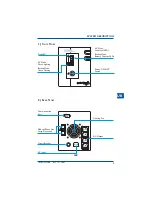
Страница 11: ...ghting Backup Mode Green Flashing Cooling Fan AC Output AC Mode Load Level LEDs Backup Mode Battery Capacity LEDs Power ON OFF Switch IEC 9 10H52164PUMC REV 1 11 2003 2 Back Panel Communication Port Modem Phone Line Surge Protection Circuit Breaker AC Input UK ...

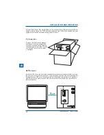
Страница 12: ... in the ON position otherwise the UPS will be disabled and your equipment will not be protected during a power failure 4 Placement Install the UPS unit in any protected environment that provides adequate airflow around the unit and is free from excessive dust corrosive fumes and conductive contaminants Do not operate your UPS in an environment where the ambient temperature or humidity is high iOn ...

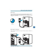
Страница 13: ...ng shipping and the battery should be recharged prior to use Plug the unit into an appropriate power supply and allow the UPS to charge fully by leaving it plugged in for at least 8 hours 6 Computer Connection Connect one computer related device into each of the power receptacles supplied on the back of the UPS 8 hours 11 10H52164PUMC REV 1 11 2003 UK ...

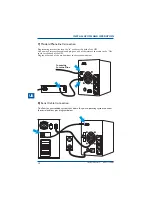
Страница 14: ...ine cable and plug one end of the internet line cable to the Out socket at the back of the UPS Plug the other end of the modem input socket as shown below 8 Serial Cable Connection To allow for unattended system shut down for your operating system connect the serial cable as per diagram below Incoming Internet line 12 10H52164PUMC REV 1 11 2003 UK ...

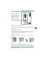
Страница 15: ... mains recovers 12 Battery Replacement Follow Chart 1 to Chart 3 to replace the battery Disconnect all sources of supply before battery replacement 13 After removing the battery cover gently extract the battery by disconnecting the two wires connecting it to Desk Power Plus Be sure to use the same type of batteries and dispose the old battery properly at an appropriate recycling facility Chart 1 R...

Страница 16: ... the specs 1 Remove some noncritical load 2 Charge battery 8 hours or more 3 Replace with the same type of battery 1 Check the setting of the software 2 Check the RS 232 cable is firmly connected to COM1 COM2 of the computer and confirm the setting again 1 Replace the same type of fuse 2 Reconnect the power cord properly Remedy 1 Missing battery 2 Battery defect 3 Power switch is not pressed at le...

Отзывы: