www.chipsee.com
www.chipsee.com
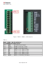
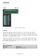
Pin 2
Isolated Ground Input
Pin 3
OUT1
Pin 4
OUT2
Pin 5
OUT3
Pin 6
OUT4
Pin 7
IN1
Pin 8
IN2
Pin 9
IN3
Pin 10
IN4
Boot Switch
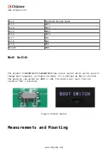
The product CS10600T101E/CS10600T101P has a boot switch which can be used to
change boot sequence, as Figure 18 shows. It is defined as SW2 on the PCB.
The position can either be eMMC or uSD. The device will boot from the
location that’s selected.
Figure 18 Boot Switch
Measurements and Mounting
Содержание CS10600T101E
Страница 1: ...www chipsee com www chipsee com EPC PPC A8 101 R User Manual Release 1 0...
Страница 5: ...www chipsee com www chipsee com CS10600T101E Figure 1 Top View...
Страница 6: ...www chipsee com www chipsee com Figure 2 Back View CS10600T101P...
Страница 7: ...www chipsee com www chipsee com Figure 3 Top View...
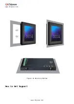
Страница 23: ...www chipsee com www chipsee com Figure 19 Mounting Method How to Get Support...


