www.chipsee.com
www.chipsee.com
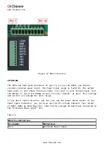
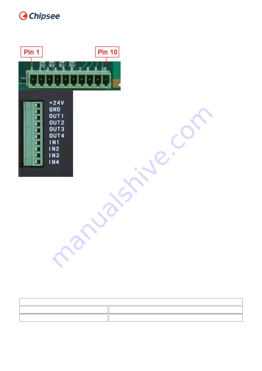
Figure 17 GPIO Connector
ATTENTION:
The GPIO has been Opto-Isolated. If you try to use the GPIO, you should
provide isolated power input. The Power Input range is 5~24V DC. The output
high Level is your Power Positive input, Low Level is your Ground Input. And
the Output it can drive 500mA current on every channel, at most. This voltage
and current are enough for most relays.
If you don’t need isolation, you can just use the power which inputs to the
Power Input Connector, you can also use the 5V voltage onboard: Just solder
on R292, R293 by 0ohm Resistor. Then the 5V voltage on-board was connected to
the “Isolated Power Input” Pin.
Table 3
GPIO Pin Definition:
Pin Number
Definition
Pin 1
Isolated Power Input
Содержание CS10600T101E
Страница 1: ...www chipsee com www chipsee com EPC PPC A8 101 R User Manual Release 1 0...
Страница 5: ...www chipsee com www chipsee com CS10600T101E Figure 1 Top View...
Страница 6: ...www chipsee com www chipsee com Figure 2 Back View CS10600T101P...
Страница 7: ...www chipsee com www chipsee com Figure 3 Top View...
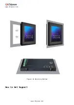
Страница 23: ...www chipsee com www chipsee com Figure 19 Mounting Method How to Get Support...


