


37 39 41
43 45 47
36 38
40 42 44
46
49
48 50
37 39 41
43 45 47
36 38
40 42 44
46
1
3
5
7
9
11 13 15 17 19 21 23 25
27 29 31 33 35
37 39 41
43 45 47
Energy
storage
Open
Close
M
Q
F
X
2
4
6
8
10 12 14 16 18 20 22 24 26 28 30 32 34
36 38 40 42 44
46
Transformer
connected
Special connecting wire
Modbus-RTU
To TO3 busbar
Red Green
L1
N
PE
1
2
Fault
51
48 50
AX
49
SB3
SB1
SB2
SA
PSU-1
~ ~
AC 220V
+ -
DC 24V
D01
DC24V
+
RU-1
D03
D02
-
DI0
D 1
I D 2
I D 3
I D 4
I
D04
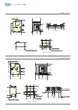
Highest-voltage of AC400V
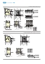
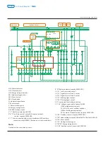
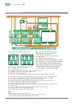
The secondary circuit wiring for NA1-2000X~6300X with type (3H) intelligent controller and instantaneous under-voltage release
The secondary circuit wiring for NA1-2000X~6300X with standard type (M) intelligent controller and time-delay under-voltage release
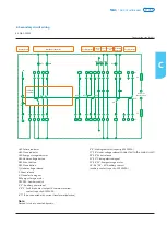
3 ,4 ,5 : Fault trip contact output(4 common terminal)
6 ,7 ,8 ,9 : Auxiliary contact(normal open)
10 ~11 : communication output
12 ,13 : Signal alarm of load 1 output; 14 ,15 : Signal alarm of load2 output
16 ,17 :Breaking signal output; 18 ,19 :Making signal output
20 : PE line; 21 : N phase input terminal
22 ,23 ,24 : A, B, C three phase power input terminal (note the sequence)(highest-voltage of AC 400V)
25 26 : Connect to the N phase current transformer or the input terminal of the current leakage transformer.
The normal products without these terminals, if the customer special ordered, the cost extra added.
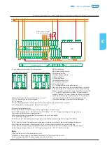
ST~DP: DP protocol module. There is no need for the ST-DP protocol module,
if the communication protocol is Modbus-RTV. But when the communication protocol is Profibus-DP,
the ST-DP protocol module is necessary, but the cost extra added.
ST power module IV: power converter (optional components)
ST201: Magnify the signal capacity of the controller. ( optional components) If the customer special ordered,
the cost extra added.
27 ,28 : Under-voltage release(
C
onnected to the main circuit)
; 29 ,30 : Shunt release
31 ,32 : Closing release; 33 ,34 : Energy storage indicator
34 ,35 : Energy storage motor; 36 ~51 : Auxiliary contact
Note:
a. Red colored part is to be connected by users
b. When the power system is three phase three wire, directly connect the Un to U2.
(If the voltage exceeds 400V, special explanation when ordered)
#
#
#
#
#
#
#
#
#
#
#
#
#
#
#
#
#
#
#
#
#
#
#
#
#
#
#
#
#
#
#
#
#
#
#
#
#
Main
circuit
Intelligent controller
Undervoltage
release
Shunt
release
Closing
electromagnet
Energy-
storage
indication
Energy-
storage
motor
Auxiliary switch
The auxiliary contact modes for customer use
Ⅱ
Five pairs change-over contacts
Ⅰ
Four pairs change-over contacts
SB1: Shunt button; SB2: Under-voltage button
SB3: Making button; Q: Under-voltage release
F: Shunt release; X: Closing release
M: Energy storage motor; XT: connection terminal
SA: Position switch
1 , 2 : Intelligent controller power input
Note: When the power supply of the intelligent controller
is AC power, the 1 ~2 connects to the AC power directly.
When the power supply is DC power, forbid connecting the
1 ~2 to the DC power directly. Add a DC power supply
module, then the DC power connect to the input terminal
of the DC power supply module, and the 1 ~2 connect to
the output terminal of the DC power supply module,
or else the intelligent controller will be damaged.
#
#
#
#
#
#
#
#
39 41
43 45 47
38
40 42 44
46 48
49
50
Failure
Energy
storage
Power
Intelligent controller
Processing
unit
FU
FU
AX
Open
Close
Under-voltage
time-delay controller
SB3
SB1
SB2
3
5
7 9
11 13 15 17 19 21 23
25 27 29
31 33 35
36 38
40 42 44
46 48 50
1 2
4
6
8
10 12 14 16 18 20 22 24
26 28 30
32
34
37 39 41
43 45 47
49 51
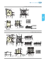
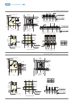
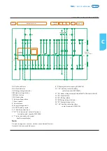
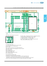
Circuit explanation for signal output:
a. Broken-line parts shall be provided by customers.
#
#
b. Terminals 6 ,7 can output NC (normal close) contact if that is required by users.
#
c. Terminal 35 can be directly connected to power (automatic pre-storing energy),
alternatively connect power after connecting NO button (manual-controlled pre-storing energy).
#
#
d. The 21 ~24 is only for wiring with function meter display. (Excluding the special wiring)
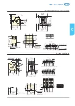
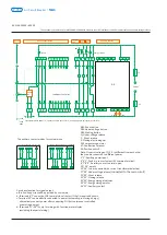
Main
circuit
Over-current release
Emergency
disconnection
Motor
driven
close
Motor
driven
break
Auxiliary switch
Intelligent release power("1” connect positive pole, and “2” connect negative pole for direct current)
110V
220V
~380V
~_
~_
Motor
driven
energy
storage
Under-voltage
time-delay
release
The auxiliary contact modes for customer use
Ⅰ
Four pairs change-over contacts
1 ,2 : Auxiliary power input
3 ,4 ,5 : Fault trip contact output(4# common terminal)
6 ,7 ,8 ,9 : Auxiliary contact(normal open)
10 ~24 : empty
25 ,26 : to be connected with current transformer(selective)
27 ,28 : Under-voltage release(
C
onnected to the main circuit)
29 ,30 : Shunt release
31 ,32 : Closing release
33 ,34 : Energy storage indicator
34 ,35 : Energy storage motor
36 ,37 : Under-voltage time delay release
38 ~51 : Auxiliary contact
#
#
#
#
#
#
#
#
#
#
#
#
#
#
#
#
#
#
#
#
#
#
#
#
#
#
#
SB1: Shunt button SB2: Under-voltage button SB3: Making button
Q: Under-voltage time-delay release F: Shunt release
X: Closing electromagnet M: Energy storage motor
XT: Connection terminal SA: Position switch
Note: If control voltage of Q, F, X is different from each other,
they can be connected to different power.
ST-DP
Profibus
24V
NC
GND
D+ D-
D+ D-
C
NA1
Air Circuit Breaker
P-062
P-061
NA1
Air Circuit Breaker
Содержание NA1
Страница 1: ...Air Circuit Breaker Leading every step reliable new height ...
Страница 2: ...Air Circuit Breaker Leading every step reliable new height ...
Страница 3: ......
Страница 4: ...Page P 001 Page P 039 ACB Air Circuit Breaker NA8G NA1 ...
Страница 45: ...P 041 NA1 Air Circuit Breaker 1 3 4 5 7 8 11 12 13 14 15 ...


