7.3 User interface of the multifunctional controller
1
2
3
4
5
6
8
7
9
10
11
12
13
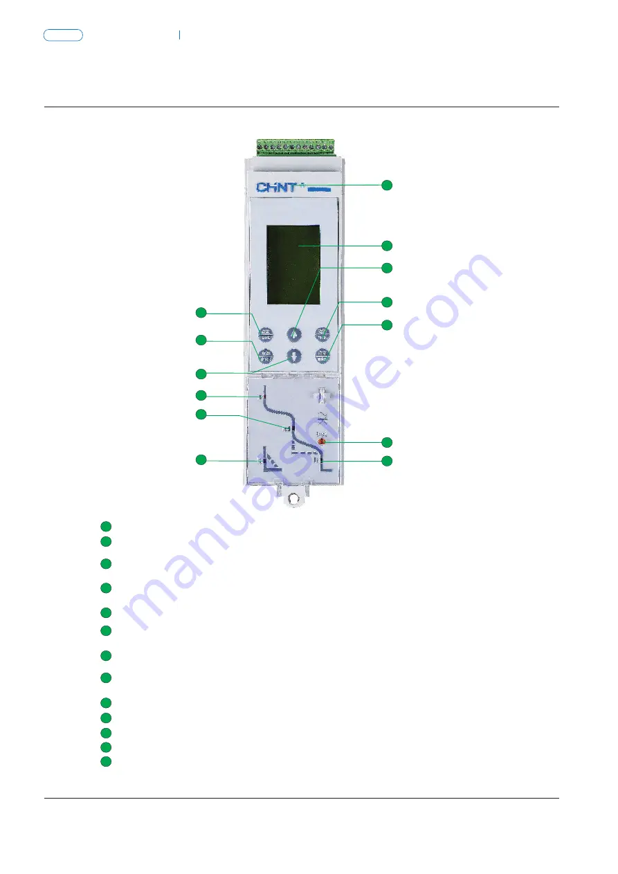
LED window
“ Ig “ limp
“ Isd “ limp
“ test ”
“ Ii “ limp
LCD window capable of showing the current for each phase, various setting parameters, rated current,
fault current, tripping time and the like
Single-phase earthing fault indicator
“ IR “ limp
Long time-delay overcurrent fault indicator
Short-circuit short time-delay overcurrent fault indicator
Button for simulating instantaneous tripping test
Short-circuit instantaneous overcurrent fault indicator
Brand
"CHINT" Brand
1
2
3
4
5
6
7
8
9
10
11
12
13
SET key
UP key
RETURN key
ACK key
DOWN key
INQUIRY key
Switch to the set default menu (left arrow key, when it is necessary to move leftwards or rightwards
for the set interface).
Move the box select menu under the current menu to change the position of said box upwards,
and perform the setting of the parameter ADD in the parameter setup menu.
Exit the current menu and go to the previous menu, or cancel the value of the current setup parameter.
Go to the next menu of the currently selected select box (go to the set state under the set interface, a
nd exit the set state by pressing the key again).
Move the box select menu under the current menu to change the position of said box downwards,
and perform the setting of the parameter SUBTRACT in the parameter setup menu.
Switch to the inquiry default menu (right arrow key, when it is necessary to move leftwards
or rightwards for the set interface).
7.4 Default interface and menu structure for the multifunctional
controller
The multifunctional controller provides 4 title menus
(measurement menu, parameter setup menu, protection
parameter setup menu, and history record and maintenance
menu) and 1 default menu.
Default interface for the multifunctional controller
Maximum
Unbalance rate
100%
Real-time value
Ia,Ib,
Ic,In
Ia
Ib
Ic
In
Ia= 1000A
Ib= 1001A
Ic= 998A
In= 0A
Ig= 0A or I
△
n=0.00A
Ia= 1300A
Ib= 1400A
Ic= 1380A
In= 200A
Ig= 0A or I
△
n=0.00A
Ia= 3%
Ib= 5%
Ic= 1%
15min
Ia= 1000A
Ib= 1000A
Ic= 998A
In= 0A
Ia= 1050A
Ib= 1040A
Ic= 1010A
In= 0A
1002A
A B C
N
150
100
50
0
7.4.1 Structure of the measurement menu
Maximum
Uab= 380V
Ubc= 380V
Uca= 380V
Uan= 220V
Ubn= 220V
Ucn= 220V
Uav= 380V
0%
A,B,C
EP= 200kWh
EQ= 10kvarh
ES= 200kVAh
EP= 200kWh
EQ= 200kvarh
EP= 0kWh
EQ= 0kvarh
Reset
Voltage U
FrequencyF
Electric energy
E
Instantaneous value
Current thermal capacitance
Required value
Instantaneous value
Mean value
Unbalance rate
Phase sequence
50Hz
Total electric energy
Input electric energy
Output electric energy
Electric energy reset
Primary menu
Secondary menu
Third
menu
Fourth
menu
Fifth
menu
Magnitude of current
Ⅰ
Air Circuit Breaker
NA8G
Air Circuit Breaker
P-026
NA8G
P-025
Содержание NA1
Страница 1: ...Air Circuit Breaker Leading every step reliable new height ...
Страница 2: ...Air Circuit Breaker Leading every step reliable new height ...
Страница 3: ......
Страница 4: ...Page P 001 Page P 039 ACB Air Circuit Breaker NA8G NA1 ...
Страница 45: ...P 041 NA1 Air Circuit Breaker 1 3 4 5 7 8 11 12 13 14 15 ...


