


Rated control supply voltage Us(V)
Operating voltage (V)
Power dissipation (W)
Energy storage time
Frequency of operation
Rated voltage(V)
AC
300VA
DC
60W
230
400
220
AC230 AC400
(0.85~1.1)Us
75/150VA
<
4s
At most 3 times in a minute
Rated thermal current Ith(A)
DC220 DC110
75/150W
Rated control capacity
6
(Inm=1600A)
(Inm=3200A,
)
6300A
6
(Inm=3200A,
)
6300A
(Inm=1600A)
9. Installation
10. Common faults and troubleshooting
2
No.
1
Breaker fails
to close
Technical problems
Breaker tripping
(fault indicator on)
Earthing fault tripping
(earthing fault indicator on)
Under voltage release
Tripping
Mechanical interlock action
Under voltage release
No attracting
Reset button fails to reset
Open frame (draw-out) circuit
breaker fails to be put to the righ
t position by rocking
Open frame (draw-out) circuit breaker
Bad contact for the secondary circuit
Breaker fails to pre-store energy
Overload fault tripping
(long time delay indicator on)
Short-circuit fault tripping
(short time-delay or
instantaneous overcurrent
indicator on)
Possible causes
1 Check the breaking current and operating time on the intelligent controller
2 Promptly find and shoot the trouble if it is confirmed that there is a earthing fault
3 If no earthing fault is detected, please determine whether the earthing fault
current setting is proper, and can be well matched with the actual protection;
if not, the setting shall be modified
4 Press the reset button to close the breaker again
1 Check to see if the power voltage is lower than 70%Ue
2 Check the under voltage release and control unit for fault
Check the working condition of two breakers equipped with mechanical interlock.
Diagnosis and trouble shooting
1 Check the breaking current and operating time on the intelligent controller
2 Analyze the operation of the load and power network
3 Promptly find and shoot the trouble if overload is confirmed
4 For lack of match between the actual running current and the long time delay
operating current, please modify the long time-delay operating current setting
for a proper match and protection according to the actual running current
5 Press the reset button to close the breaker again
1 Check the breaking current and operating time on the intelligent controlle
2 Promptly find and shoot the trouble if overload is confirmed
3 Check the setting value of the intelligentcontroller
4 Check to see whether the breaker is in good condition, and determine whether
it can be closed for operation
5 Press the reset button to close the breaker again
Closing electromagnet trouble
1 Whether the under voltage release has been energized
2 Whether the power voltage is lower than 85%Ue
3 Whether the under voltage release or control unit malfunctions,
if so, the release shall be replaced.
Press the reset button to close the breaker again.
Put the open frame (draw-out) circuit breaker to the right position
by rocking (with it locked in the connected position)
Check the contract status of the secondary circuit,
and shoot the trouble, if any
1 Check the motor control power supply and see if it is well
providing power, and the voltage must be
≥
85%Us
2 Check the status of the motor energy storage mechanism.
1 Check the power voltage of the closing electromagnet,
and it must be higher than or equal to 85%Us
2 If there is any trouble in the closing electromagnet to enable the attracting,
it shall be replaced.
NA8G
Air Circuit Breaker
P-036
P-035
NA8G
Air Circuit Breaker
9.1
Following
items
to
be
checked
before
installation
Check
the
label
plate
on
the
breaker
panel
to
see
if
it
is
conform
to
the
specifications
of
the
ordered
goods
.
a
.
Rated
current
b
.
Under
voltage
release
voltage
and
delay
time
c
.
Shunt
release
voltage
d
.
Closing
electromagnet
voltage
e
.
Motor
voltage
9.2
Before
installation
,
operation
,
maintenance
and
inspection
,
you
shall
read
this
manual
,
and
consult
the
manufacturer
for
questions
,
if
any
.
9.3
Preparations
before
installation
Before
the
breaker
is
installed
,
check
the
insulation
resistance
of
the
breaker
by
using
a
1000
V
megohmmeter
according
to
regulations
;
when
the
surrounding
media
temperature
is
25℃±5℃
and
the
relative
humidity
50% - 70%,
the
insulation
resistance
shall
not
be
less
than
20
megohm
.
The
place
with
the
insulation
resistance
to
be
tested
includes
:
the
place
between
various
phases
and
between
various
phases
and
the
frame
when
the
breaker
is
closed
;
the
place
between
in
-
and
out
-
lines
of
various
phases
.
Listed below are the problems which users may encounter
during installation, adjustment, and operation of the breaker,
and the possible reasons and elimination methods.
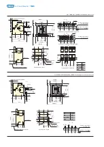
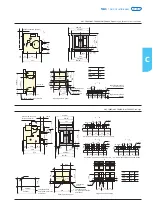
9.4 Installation of the fixed type breaker
Place the breaker into the distribution cabinet, and fasten it
by using 4 pieces of M6(In=1600A) or M10(In=3200A or
more) bolts and washers. The breaker shall be installed stably
with no additional mechanical stress to avoid damage of the
breaker or bad contact of the main bus bar.
9.5 Installation of the open frame (draw-out) circuit breaker Take
the breaker body out of the draw-out socket, and install the
socket in the distribution cabinet, and fasten it by using 4
pieces of M6(In=1600A) or M10(In=3200A or more) bolts and
washers; the breaker shall be installed stably with no
additional mechanical stress to avoid damage of the breaker
or bad contact of the main bus bar. After the work is
completed, mount the body into the draw-out socket.
9.6 The specifications of the wiring copper bars for the primary
circuit of the breaker shall meet the copper bar specifications
used under the conditions of conventional heating in IEC/EN
60947-2.
9.7 The breaker shall be grounded substantially.
8.4 Motor-driven energy storage mechanism
The functions of motor-driven energy storage and automatic energy
re-storage after the breaker comes on are available to ensure that
the breaker can come on immediately after it gets
8.6 Phases barrier
Phases barrier is installed between the phases of the line bank to improve the
insulating ability between the phases of the breaker
.
8.7 Key lock
The OFF pushbutton of the breaker can be locked in the position of depress,
and at this time, the breaker cannot be closed for operation; When the user
selects the option, the factory provides locks and keys; One breaker is provided
with one lock and one key for the lock; Two breakers are two provided with
locks and one key for the locks; Three breakers are provided with three same
locks and two same keys for the locks.
Note:
For the air circuit breaker with key lock, when the key has to be pulled out, it is
necessary to first press the OFF key, turn the key anticlockwise, and then pull
out the key.
8.8 Button locking device
It is used to lock the button for opening and closing the breaker with the
padlock used for such a purpose. (Padlock is provided by users themselves)
8.9 Doorcase
They are installed on the door of the distribution cabinet room to seal it with a
protection level of up to IP40.
8.10 “Disconnected” pation locking device for the draw-out.
For the “separation” position of the open frame (draw-out) circuit breaker, a
lock rod can be pulled out to lock the matter, and the breaker locked will be
unable to be turned towards the TEST or CONNECTION position. Padlocks
have to be provided by users themselves.
8.11 Three-position locking device for the draw-out.
After the breaker body is locked automatically in any working position, it is
necessary to turn the key to unlock the matter so that the break body can be
moved to the next working position by turning the handle. (this function
available for 3200 to 6300).
8.12 Door interlock
Door interlock for the breaker status
When the breaker is closed, the cabinet door must not be opened; when the
breaker is switched off, the cabinet door is allowed to be opened. Door
interlock for the breaker position When the breaker is in the position of
connection and test, the cabinet door must not be opened; when the breaker
is the separation position, the cabinet door is allowed to be opened.
8.13 Mechanical interlock
It can realize the interlock of two horizontal or vertical-installed,three poles or
four poles,drawout or fixed breakers.
8.5 Auxiliary contact
Standard type:4 switch contact
Special type:5 switch contact
6 switch contact (Only for I =1600A, and not available for DC)
nm
3 N.O. and 3 N.C.
4 N.O. and 4 N.C.(I =3200A and 6300A provided)
nm
disconnected.Operating characteristic:
Technical parameters:
Содержание NA1
Страница 1: ...Air Circuit Breaker Leading every step reliable new height ...
Страница 2: ...Air Circuit Breaker Leading every step reliable new height ...
Страница 3: ......
Страница 4: ...Page P 001 Page P 039 ACB Air Circuit Breaker NA8G NA1 ...
Страница 45: ...P 041 NA1 Air Circuit Breaker 1 3 4 5 7 8 11 12 13 14 15 ...


