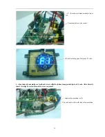


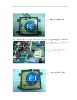
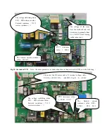

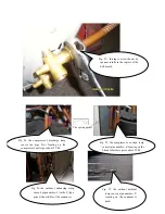


Fig. 11
:
the outdoor PCB
2
,
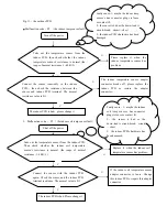
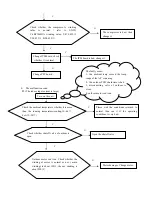
Malfunction code
:
F2
(
the indoor temp sensor fault
)
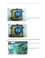
3
,
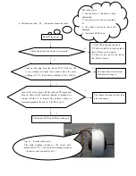
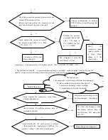
Malfunction code
:
F3
(
the indoor coil temp sensor fault
)
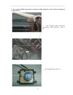
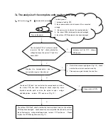
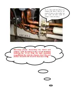
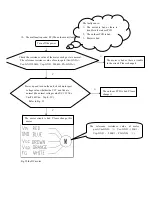
Turn off the power
Take out the temperature sensor from the
indoor PCB, then check whether the indoor
temperature sensor’s resistance is normal.(the
range of normal resistance :1~40 K
Ω
)
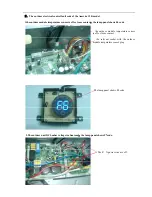
N
Please replace it .when the
indoor temperature sensor has
problem.
Y
Connect the sensor renewedly to the indoor
PCB,
,
then check the resistance between the
sensor and indoor PCB terminal. The normal
resistance value is 0
Ω
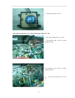
N
The indoor temperature sensor adapter
connector breaks off, please replace the
indoor PCB or restore the adapter
connector.
。
Y
The indoor PCB is bad
,
please change it
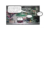
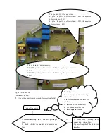
F
aulty cause
:
1
、
maybe the indoor temp
sensor’s bnc connector plugs is loose
or contact ill;
2
、
the sensor is bad or the down-lead is
circuit-break
、
circuit
-
short
3
、
the indoor PCB’s hardware has been
damaged
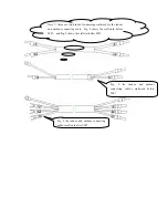
Faulty cause
:
1
、
maybe the indoor
coil temp sensor’s bnc connector
plugs is loose or contact ill;
2
、
the sensor is bad or the
down-lead is circuit-break
、
circuit
-
short
3
、
the indoor PCB’s hardware has
been damaged
Shut off the power
Take out the temperature sensor from the indoor PCB,
Then check whether the indoor coil temperature
sensor’s resistance is normal. (the range of normal
resistance :1~40 K
Ω
)
N
Replace it .when the indoor coil
temperature sensor has problem.
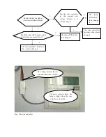
Y
Connect the sensor with the indoor PCB
again. Check the sensor and the indoor PCB
terminal resistance. The normal value is 0
Ω
N
If the indoor coil temperature sensor
adapter connector is loose. Change
this indoor PCB or repair this adapter
connector
Y
The indoor PCB is bad. Please change it.
Содержание CS-25V1A-H1; CS-35V1A-E2; CS-50V9A-S; CS-70V9A-T
Страница 1: ...DC Inverter Split Air Condition Unit SERVICE MANUAL ...
Страница 3: ...3 1 Air conditioning unit parameters ...
Страница 6: ...6 ...
Страница 8: ...8 The curve diagram of the compressor condensing pressure ...
Страница 12: ...12 Capacity Correction Factor Due to Tubing Length One Way Cooling Heating ...
Страница 13: ...13 Pressure Curve Suction Pressure Curve Discharge Pressure Curve ...
Страница 15: ...15 4 Indoor and outdoor units size 4 1 outdoor Unit CS 25V1A H1 4 2 outdoor Unit CS 35V1A E2 ...
Страница 16: ...16 4 3 outdoor Unit CS 50V9A S 4 4 outdoor Unit CS 70V9A T ...
Страница 19: ...19 ...
Страница 20: ...20 5 2 The explosion diagram and spare parts list for CS 25V1A M81A ON OFF ...
Страница 21: ...21 ...
Страница 22: ...22 5 3 The explosion diagram and spare parts list for CS 35V1A E2 ...
Страница 23: ...23 ...
Страница 24: ...24 5 4 The explosion diagram and spare parts list for CS 35V1A P81A ON 0FF F ...
Страница 25: ...25 ...
Страница 26: ...26 5 5 The explosion diagram and spare parts list for CS 50V9A S ...
Страница 27: ...27 ...
Страница 28: ...28 5 6 The explosion diagram and spare parts list for CS 50V9A S81A ON 0FF F ...
Страница 29: ...29 ...
Страница 30: ...30 5 7 The explosion diagram and spare parts list for CS 70V9A T ...
Страница 31: ...31 ...
Страница 32: ...32 5 8 The explosion diagram and spare parts list for CS 50V9A S ...
Страница 33: ...33 ...
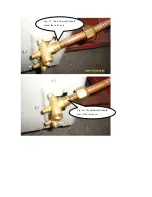
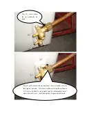
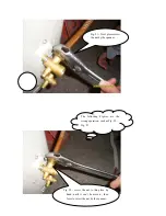
Страница 60: ...Fig 17 the bell mouth should aim at the valve port Fig 18 the bell mouth should aim at the valve port ...


