14
E L E C T R I C A L D ATA
Model
CS-25V1A-H1
Power Supply
1 PH, 115 VAC,60Hz
Connected to
Outdoor
Maximum Current
9.3A
Inrush Current
40A
Starting Current
1A
Circuit breaker
20A
Power supply wiring - No. x cross section
1 X 3 X 2.5 mm
2
Interconnecting cable - No. x cross section
2 X 4 X 1 mm
2
Model
CS-35V1A-E2
Power Supply
1 PH, 115 VAC,60Hz
Connected to
Outdoor
Maximum Current
10.8A
Inrush Current
40A
Starting Current
1A
Circuit breaker
20A
Power supply wiring - No. x cross section
1 X 3 X 2.5 mm
2
Interconnecting cable - No. x cross section
2 X 4 X 1 mm
2
Model
CS-50V9A-S
Power Supply
1 PH, 230 VAC,60Hz
Connected to
Outdoor
Maximum Current
10.1A
Inrush Current
40A
Starting Current
1A
Circuit breaker
20A
Power supply wiring - No. x cross section
1 X 3 X 2.5 mm
2
Interconnecting cable - No. x cross section
2 X 4 X 1 mm
2
Model
CS-70V9A-T
Power Supply
1 PH, 230 VAC,60Hz
Connected to
Outdoor
Maximum Current
12.2A
Inrush Current
35A
Starting Current
1A
Circuit breaker
20A
Power supply wiring - No. x cross section
1 X 3 X 2.5 mm
2
Interconnecting cable - No. x cross section
2 X 4 X 1 mm
2
Содержание CS-25V1A-H1; CS-35V1A-E2; CS-50V9A-S; CS-70V9A-T
Страница 1: ...DC Inverter Split Air Condition Unit SERVICE MANUAL ...
Страница 3: ...3 1 Air conditioning unit parameters ...
Страница 6: ...6 ...
Страница 8: ...8 The curve diagram of the compressor condensing pressure ...
Страница 12: ...12 Capacity Correction Factor Due to Tubing Length One Way Cooling Heating ...
Страница 13: ...13 Pressure Curve Suction Pressure Curve Discharge Pressure Curve ...
Страница 15: ...15 4 Indoor and outdoor units size 4 1 outdoor Unit CS 25V1A H1 4 2 outdoor Unit CS 35V1A E2 ...
Страница 16: ...16 4 3 outdoor Unit CS 50V9A S 4 4 outdoor Unit CS 70V9A T ...
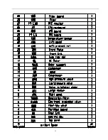
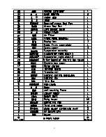
Страница 19: ...19 ...
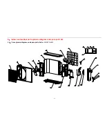
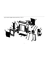
Страница 20: ...20 5 2 The explosion diagram and spare parts list for CS 25V1A M81A ON OFF ...
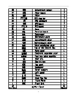
Страница 21: ...21 ...
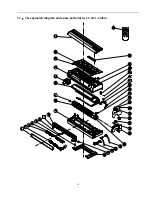
Страница 22: ...22 5 3 The explosion diagram and spare parts list for CS 35V1A E2 ...
Страница 23: ...23 ...
Страница 24: ...24 5 4 The explosion diagram and spare parts list for CS 35V1A P81A ON 0FF F ...
Страница 25: ...25 ...
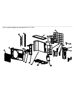
Страница 26: ...26 5 5 The explosion diagram and spare parts list for CS 50V9A S ...
Страница 27: ...27 ...
Страница 28: ...28 5 6 The explosion diagram and spare parts list for CS 50V9A S81A ON 0FF F ...
Страница 29: ...29 ...
Страница 30: ...30 5 7 The explosion diagram and spare parts list for CS 70V9A T ...
Страница 31: ...31 ...
Страница 32: ...32 5 8 The explosion diagram and spare parts list for CS 50V9A S ...
Страница 33: ...33 ...
Страница 60: ...Fig 17 the bell mouth should aim at the valve port Fig 18 the bell mouth should aim at the valve port ...


