Chigo CS-25V1A-H1; CS-35V1A-E2; CS-50V9A-S; CS-70V9A-T Скачать руководство пользователя страница 23


23


Содержание CS-25V1A-H1; CS-35V1A-E2; CS-50V9A-S; CS-70V9A-T

Страница 1: ...DC Inverter Split Air Condition Unit SERVICE MANUAL ...

Страница 2: ...orking conditions and temperature range 2 1 3 Units characteristic 3 1 4 Indoor and outdoor units size 4 1 5 Indoor and outdoor unit explosion diagram and spare parts list 5 1 6 The analysis of indoor malfunction code 6 1 7 The analysis of the complete units malfunction code 7 1 ...

Страница 3: ...3 1 Air conditioning unit parameters ...

Страница 4: ...e with ANSI AHAM RAC 1 2003 and UL 484 Cooling Indoor 80o FDB 67o F WB Outdoor 95o F DB 75o F WB Heating Indoor 70 o F DB 60 o F WB Outdoor 47o F DB 43 o F WB 2 2 Operating Limits Outdoor Upper limit DB 110 o F Cooling Lower limit DB 5o F Upper limit DB 75 o F Heating Lower limit DB 5o F 2PH 198 264V 115V Voltage 3PH N A ...

Страница 5: ...nit We leaded to adapt 180 sine wave with permanently magnetic and synchronized Brushless motor compressor motivated from 120 square wave control to 180 sine wave These contribute higher efficiency lower power consumption and noise Compressor motivated by 180 sine wave High precision of flow control valve Compared with the on off unit DC inverter with large range of flow accurate has the advantage...

Страница 6: ...6 ...

Страница 7: ... a high efficiency DC inverter technology outdoor unit its SEER is as high as 21 for the 12K unit when compared to SEER13 it can save electricity 38 in a year The curve diagram of the compressor energy consumption COP W W 2ND ...

Страница 8: ...8 The curve diagram of the compressor condensing pressure ...

Страница 9: ...0 73 0 75 0 76 0 77 TC 11040 11808 12576 13296 14064 SC 10118 10361 10542 10785 10966 86 PI 0 81 0 82 0 83 0 85 0 86 TC 10464 11232 12000 12768 13536 SC 9876 10058 10300 10542 10724 95 PI 0 88 0 90 0 92 0 93 0 94 TC 9936 10704 11424 12192 12960 SC 9634 9815 10058 10239 10482 104 PI 0 97 0 98 0 99 1 01 1 02 TC 9264 10032 10752 11520 12288 SC 9270 9512 9694 9936 10118 115 PI 1 07 1 08 1 09 1 11 1 13...

Страница 10: ...0 20 18 PI 0 91 0 97 1 04 TC 11060 10500 9800 30 28 PI 0 96 1 02 1 08 TC 11340 10640 10080 36 34 PI 0 99 1 06 1 12 TC 14560 14000 13440 45 43 PI 1 04 1 11 1 18 TC 15400 14840 14140 50 48 PI 1 11 1 18 1 25 TC 16240 15680 14980 59 54 PI 1 16 1 22 1 30 TC 85 105 of nominal 59 75 Protection Range PI 80 120 of nominal L E G E N D TC Total Cooling Capacity BTU SC Sensible Capacity BTU PI Power Input kW ...

Страница 11: ...io Vs Outdoor Temperature Cooling Capacity Correction Factor 0 0 2 0 4 0 6 0 8 1 1 2 1 4 77 86 95 104 115 Outdoor Temp deg F Capacity Ratio 90 73 84 70 81 66 75 63 72 59 Heating Capacity Correction Factor 0 0 2 0 4 0 6 0 8 1 1 2 1 4 5 14 20 30 36 45 50 59 Outdoor Temp deg F Capacity Ratio 59 68 77 ...

Страница 12: ...12 Capacity Correction Factor Due to Tubing Length One Way Cooling Heating ...

Страница 13: ...13 Pressure Curve Suction Pressure Curve Discharge Pressure Curve ...

Страница 14: ... Power supply wiring No x cross section 1 X 3 X 2 5 mm2 Interconnecting cable No x cross section 2 X 4 X 1 mm2 Model CS 50V9A S Power Supply 1 PH 230 VAC 60Hz Connected to Outdoor Maximum Current 10 1A Inrush Current 40A Starting Current 1A Circuit breaker 20A Power supply wiring No x cross section 1 X 3 X 2 5 mm2 Interconnecting cable No x cross section 2 X 4 X 1 mm2 Model CS 70V9A T Power Supply...

Страница 15: ...15 4 Indoor and outdoor units size 4 1 outdoor Unit CS 25V1A H1 4 2 outdoor Unit CS 35V1A E2 ...

Страница 16: ...16 4 3 outdoor Unit CS 50V9A S 4 4 outdoor Unit CS 70V9A T ...

Страница 17: ...nit mm Machine body size mounting dimensions Size symbol Indoor model A B C D E F CS 25V1A M 800 280 195 490 CS 35V1A P 900 296 220 583 257 5 257 5 CS 50V9A S W 1068 1080 325 305 240 214 700 696 305 305 315 315 CS 70V9A Q 1225 325 245 685 311 5 311 5 ...

Страница 18: ...18 5 Indoor and outdoor unit explosion diagram and spare parts list 5 1 The explosion diagram and spare parts list for CS 25V1A H1 ...

Страница 19: ...19 ...

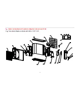
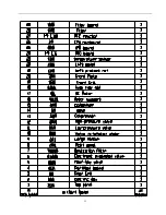
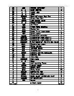
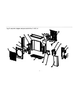
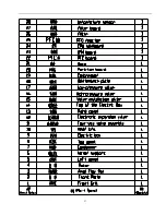
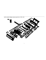
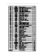
Страница 20: ...20 5 2 The explosion diagram and spare parts list for CS 25V1A M81A ON OFF ...

Страница 21: ...21 ...

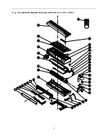
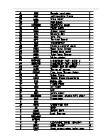
Страница 22: ...22 5 3 The explosion diagram and spare parts list for CS 35V1A E2 ...

Страница 23: ...23 ...

Страница 24: ...24 5 4 The explosion diagram and spare parts list for CS 35V1A P81A ON 0FF F ...

Страница 25: ...25 ...

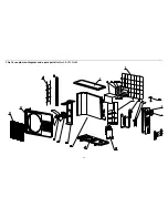
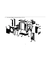
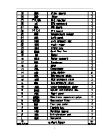
Страница 26: ...26 5 5 The explosion diagram and spare parts list for CS 50V9A S ...

Страница 27: ...27 ...

Страница 28: ...28 5 6 The explosion diagram and spare parts list for CS 50V9A S81A ON 0FF F ...

Страница 29: ...29 ...

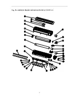
Страница 30: ...30 5 7 The explosion diagram and spare parts list for CS 70V9A T ...

Страница 31: ...31 ...

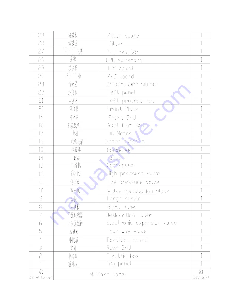
Страница 32: ...32 5 8 The explosion diagram and spare parts list for CS 50V9A S ...

Страница 33: ...33 ...

Страница 34: ... malfunction 1 when indoor unit live wire is disconnected its lamp panel can t display Live wire is off 2 when the transformer s secondary and primary disconnect or indoor fuse is off the indoor unit lamp panel can t display Transformer secondary is off Transformer primary is off The relevant transfomer primary socket ...

Страница 35: ...The condition that the lamp panel can t display 3 1 when the indoor null line is off the system displays F1 code 2 when indoor communication wire is off the system also displays F1 code The inserted slice to null line The indoor unit null line is off ...

Страница 36: ... the indoor lamp panel displays F1 code 4 when indoor fan mainline or feedback wire is off the indoor lamp panel displays F4 code After directly insert it well To restart the unit to recover normal Indoor fan mainline is off The relevant socket with indoor fan mainline ...

Страница 37: ...ensor has the problem the lamp will display F2 F3 code When indoor coil outlet inlet and middle temperature sensor appear malfunction the lamp panel displays F3 code when indoor temperature sensor appears fault the lamp panel shows F2 fault code Indoor temperature sensor plug the relevant socket of indoor temperature sensor plug ...

Страница 38: ...ly displays F2 F3 fault code 6 when outdoor temperature sensor is off or loose contact the indoor lamp panel displays F6 fault code the relevant socket of outdoor temp sensor The outdoor temperature sensor is off or loose contact ...

Страница 39: ...6 fault code 7 when the system appears mode conflict the indoor lamp panel shows d1 code the indoor lamp panel shows d1 code 8 when the system is in the defrosting condition The lamp panel displays dF code The lamp panel displays dF code ...

Страница 40: ...s off or loose contact the lamp panel shows F6 code the outdoor module temperature sensor is off or loose contact the relevant socket with the outdoor module temperature sensor plug The lamp panel shows F6 code 2 The outdoor unit DC busbar voltage is abnormal the lamp panel shows F7code The P N power wire are off ...

Страница 41: ...door module drive wire is off the lamp panel shows FC code The outdoor module drive wire is off The matching socket with the outdoor module drive wire The matching socket with the outdoor module drive wire The outdoor module drive wire is off ...

Страница 42: ...rd and mainboard power wire is off or loose contact the lamp panel shoes F1 code the wave filtering board and mainboard power wire is off or loose contact The matching socket with the wave filtering board and mainboard power wire the lamp panel shoes F1 code ...

Страница 43: ...rator middle temperature and condenser middle temperature sensor is off the lamp panel displays P8 code the evaporator middle temperature and condenser middle temperature sensor is off the lamp panel displays P8 code ...

Страница 44: ...r anti cold air The timing lamp lightens 1 time and then extinguish 1 second The outdoor unit faulty display Faulty contents Trouble display the outdoor unit transducer module protection faulty The timing lamp lightens all the time the turbo lamp lightens 2 times and then extinguish 2 seconds over current of outdoor unit The timing lamp lightens all the time the turbo lamp lightens 3 times and the...

Страница 45: ...i cold air The running lamp lightens 1 time and then extinguish 1 second Faulty contents Trouble display the outdoor unit transducer module protection faulty The running lamp lightens all the time the sleeping lamp lightens 2 times and then extinguish 2 seconds over current of outdoor unit The running lamp lightens all the time the sleeping lamp lightens 3 times and then extinguish 2 seconds disch...

Страница 46: ... Malfunction code F1 communications issue Y Turn on the power 1 Refer to the connecting diagram Fig 1 9 check whether the wire is connected correctly 2 Please screw again to make the wire firm Whether the communication wire is connected wrongly or disentwined N Y Change indoor PCB N The outdoor PCB fault check whether the communication circuit on the outdoor PCB has been damaged check especially s...

Страница 47: ...ue wire is N Fig 1 check the voltage between the point of P and N whether is about 300V P is anode N is cathode If the voltage between P and N is 0 V means that PFC is damaged please change PFC This board is PFC board ...

Страница 48: ...the indoor and outdoor connecting cable Fig 8 shows the craftwork before 2007 and Fig 9 shows the craftwork after 2007 Fig 8 the indoor and outdoor connecting cable s craftwork before 2007 Fig 9 the indoor and outdoor connecting cable s craftwork after 2007 ...

Страница 49: ...istance value 1 02KΩ 25 The limited current resistance value 14 8 kΩ The voltage stabilizing diode ZD1 ZD2 reference value Forward resistance 713Ω reverse resistance PTC1 resistance value 1 02KΩ 25 The limited current resistance value R54 0 76kΩ R58 2 kΩ The voltage stabilizing diode ZD1 ZD2 reference value Forward resistance 713 Ω reverse resistance Please test the DC motor end to N terminal volt...

Страница 50: ...door temp sensor s bnc connector plugs is loose or contact ill 2 the sensor is bad or the down lead is circuit break circuit short 3 the indoor PCB s hardware has been damaged Faulty cause 1 maybe the indoor coil temp sensor s bnc connector plugs is loose or contact ill 2 the sensor is bad or the down lead is circuit break circuit short 3 the indoor PCB s hardware has been damaged Shut off the pow...

Страница 51: ...gradually from 0 to 2 4VDC Fig 10 N The indoor fan motor is bad then please change it Y The indoor PCB is bad Please change it Check the indoor fan whether it is smooth N 1 If the fan is bad and change it 2 The bolt what fix the indoor fan is loose Please screw it again 3 There are any dirt in the indoor fan Please clean it Y The faulty cause 1 the fan motor is blocked or turns abnormally 2 the mo...

Страница 52: ...is 0Ω N The indoor temperature sensor adapter connector is loose Change this indoor PCB or repair this adapter connector Y The indoor PCB is bad Please change it Electrify and turn on the unit Check the connecting line wire controller PCB whether they are loose or have a bad contact Y Please change the connecting line or repair the loose terminal N Faulty cause 1 maybe the indoor coil temp sensor ...

Страница 53: ...re is bad please change it Test the wire controller to the ground wire voltage whether it is 5VDC Fig 13 Check whether the light of the wire controller is bright N Y N The indoor PCB is bad then change it N The indoor PCB is bad then change it The voltage between the red wire and white wire 5VDC The power indicator lamp the lamp is bright when the wire controller is electrified ...

Страница 54: ...Q3 reference value be pole The positive pole resistance 660Ω the negative pole resistance 961Ω bc pole The positive pole resistance 659Ω the negative pole resistance 1439Ω The clamping diode s parameter VD15 The positive pole resistance 389Ωthe negative pole resistance 392Ω VD16 The positive pole resistance 497Ωthe negative pole resistance 1012Ω The faulty cause 1 the compressor s connecting wirin...

Страница 55: ...hot 15 24 Y Please wait the conditions returned to normal then run it if the operating conditions is very bad The faulty cause 1 the ambient temp exceed the temp range of the A C s running 2 the outdoor PCB s hardware is bad 3 disconnecting valve of outdoor is close 4 outdoor motor can t run Change PFC board N Y The IPM board is bad change it Outdoor motor can t run Check whether the winding of mo...

Страница 56: ...t out The outdoor PCB is bad Please change it Y Whether the pressure is normal the normal value the high is 2 4 3 06MPa the low is 1 2 1 6MPa N Check the compressor phase current whether it is large Please change it if the value is large Y Turn off the power Check whether the compressor crustal temp switch is disconnected Y Compressor crustal temp switch has been damaged then change it N Check whe...

Страница 57: ...s been damaged N 1 Change the temp sensor 2 Firm the module and radiator 3 Append anew the disperse heat silica gel 4 Change the module Y Please change the outdoor PCB Turn off the supply Check whether the power voltage is in the normal voltage range 150V 270V N Ensure the power voltage is in the normal voltage range 150V 270V Y The IPM basic board hardware has been damaged please change the IPM b...

Страница 58: ...pen N Open the high and low pressure valve Check whether the system pressure is normal the normal value high pressure3 06Mpa low pressure1 6Mpa N Due to refrigerant leakage kook for the leak to weld it then charge anew the refrigerant to the system Fig 9 17 Please change it if the sensor wire is short circuit or open circuit N Y Check whether the indoor and outdoor pipe temp sensor are loose or ha...

Страница 59: ...e bubbles that grow slowly and broke around the terminal it shows the leakage Warning please connecting the indoor and outdoor units according to the correct installing method Fig 17 21 show the right operating way Note the indicator figures aren t the real photos about the DC inverter dual zone unit ...

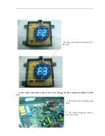
Страница 60: ...Fig 17 the bell mouth should aim at the valve port Fig 18 the bell mouth should aim at the valve port ...

Страница 61: ...ig 20 please screw the nut until can t move by hand refer to the Figure s position If not move when screwing the nut about 3 4 circles by hand it is possible that the bell mouth doesn t aim at the valve port and then operate it again from scratch ...

Страница 62: ...please screw the nut by the spanner Fig 22 screw the nut to this place by hand until it can t be moved then force to screw the nut by the spanner The following Figures are the wrong operation such as Fig 22 Fig 23 ...

Страница 63: ...tion temp sensor pipe number 4 locating on the Shock Absorbers piece above 5CM Fig 26 the outdoor condensing temp sensor pipe number 3 in the U type pipe at the middle of the condenser Fig 27 the outdoor ambient temp sensor pipe number 2 locating on the condenser s back Fig 23 forcing to screw the nut by spanner results in the rupture of the bell mouth ...

Страница 64: ...number 4 Fig 28 3 The indoor evaporator s inlet temp sensor pipe number 2 Fig 29 The indoor ambient temp sensor pipe number 1 Note Apart from the ambient temperature sensor all sensors must be equipped with spring washer please check it by Fig If the angle is similar to Fig 24 means that spring has lost its elasticity please bend it to an angle of 135 degrees Re Fig 8 Please ensure to install them...

Страница 65: ...rcuit Please change it Y Power up and turn on the unit check motor port voltage value whether the VCC and Vm are normal the normal voltage value VCC 15Vdc Vm P 340Vdc Vsp 0 5V Refer to Fig 32 Y The outdoor PCB is bad Please change it The motor circuit is bad Please change this motor N The faulty cause 1 The motor is bad or there is trouble in the indoor PCB 2 The outdoor PCB is bad 3 Motor is bad ...

Страница 66: ...by crabstick Let the rotor become be loose then turn on it again and check the compressor whether it is running Y The start up moment isn t enough because of the first running This is a normal Y Check the contacting wire of compressor whether it is right or credible N Please contact the wire exactly again according to Figure if there is a mistake The component of IPM board is bad Please change it ...

Отзывы: