PXR
Installation Instructions
20
2.
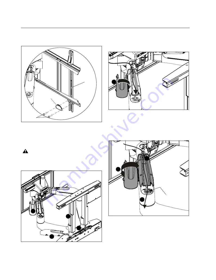
Lock display with attached interface brackets to PXR using
two bracket locks (W) and four 1/4-20 x 1/2" hex head cap
screws (U). (See Figure 31) and (See Figure 33)
Figure 33
Cable Management
NOTE:
Available points of cable management are illustrated
(See Figure 34) and specifically called out in the
following instructions and figures.
CAUTION:
PXR SHOULD ONLY BE MOVED USING
REMOTE CONTROL!! After the PXR arms have been
engaged, do NOT move PXR by hand!
Figure 34
IMPORTANT ! :
If possible, place display’s power and
signal cables in separate PXR arms.
1.
Open cable management covers on top of both PXR arms.
(See Figure 34) and (See Figure 35)
Figure 35
2.
Extend cables from display and lay cables within top of
arms. (See Figure 36)
3.
Close cable management covers, being careful to not pinch
cables under covers. (See Figure 36)
Figure 36
4.
Continue cable down outside of arms.
NOTE:
Do NOT route cables through center pin. (See Figure 36)
(U)
(W)
(V)
(view from back of PXR)
7
8
5
(Display removed for clarity)
1
1
2
4
3
Do NOT route
cable through
center pin.
Содержание PXR
Страница 29: ...Installation Instructions PXR 29 ...
Страница 30: ...PXR Installation Instructions 30 ...
Страница 31: ...Installation Instructions PXR 31 ...


