


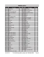

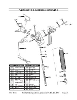

SKU 66745
For technical questions, please call 1-800-444-3353.
Page 8
some dust and fumes created by
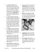
18.
painting, power sanding, sawing,
grinding, drilling, and other con-
struction activities, contains chem-
icals known [to the state of califor-
nia] to cause cancer, birth defects
or other reproductive harm. some
examples of these chemicals are:
• Lead from lead-based paints
• Crystalline silica from bricks and ce
-
ment or other masonry products
• Arsenic and chromium from chemi
-
cally treated lumber
Your risk from these exposures var-
ies, depending on how often you do
this type of work. To reduce your
exposure to these chemicals: work in
a well ventilated area, and work with
approved safety equipment, such as
those dust masks that are specially
designed to filter out microscopic
particles. (California Health & Safety
Code § 25249.5,
et seq.
)
Warning: the brass compo-
19.
nents of this product contain lead,
a chemical known to the state of
california to cause birth defects (or
other reproductive harm).
(California Health & Safety Code §
25249.5, et seq.)
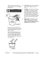
Warning: handling the power
20.
cord (37a) on this product will
expose you to lead, a chemical
known to the state of california to
cause cancer, and birth defects or
other reproductive harm.
Wash hands after handling.
(California Health & Safety Code §
25249.5, et seq.)
the warnings, precautions, and
21.
instructions discussed in this in-
struction manual cannot cover all
possible conditions and situations
that may occur.
It must be under-
stood by the operator that common
sense and caution are factors which
cannot be built into this product, but
must be supplied by the operator.
saVe these
instructiOns.
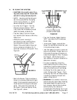
grOunding
tO preVent
electric shOcK
and death FrOm
incOrrect grOunding
Wire cOnnectiOn:
Check with a qualified
electrician if you are in doubt
as to whether the Outlet is
properly grounded. do not
modify the power cord plug
provided with the tool. never
remove the grounding prong
from the plug. do not use the
tool if the power cord or plug
is damaged. if damaged,
have it repaired by a service
facility before use. if the plug
will not fit the Outlet, have a
proper Outlet installed by a
qualified electrician.


