background image

Page 10

For equipment technical questions, please call 1-888-866-5797. 

For engine technical questions, please call 1-800-520-0882.

ITEM 61924 


SAFETY

SETUP

O

PERA

TION

M

AINTENANCE

Break-in Period:

a.  Breaking-in the engine will help to ensure 

proper equipment and engine operation.

b.  The operational break-in period will last 

about 3 hours of use.  During this period:

•  Do not apply a heavy load to the equipment.
•  Do not operate the engine at 

its maximum speed.

c.  The maintenance break-in period 

will last about 20 hours of use.

•  Change the engine fuel/oil 

mixture after this period.

Under normal operating conditions subsequent 

maintenance follows the schedule explained 

in the MAINTENANCE section.

General Operating Instructions

TO PREVENT SERIOUS INJURY: 

Wear ANSI-approved safety goggles, ear protection, steel-toe boots, and dust mask during use.   

Keep feet clear of Breaker Hammer.   

Keep children and animals well clear of the work area.

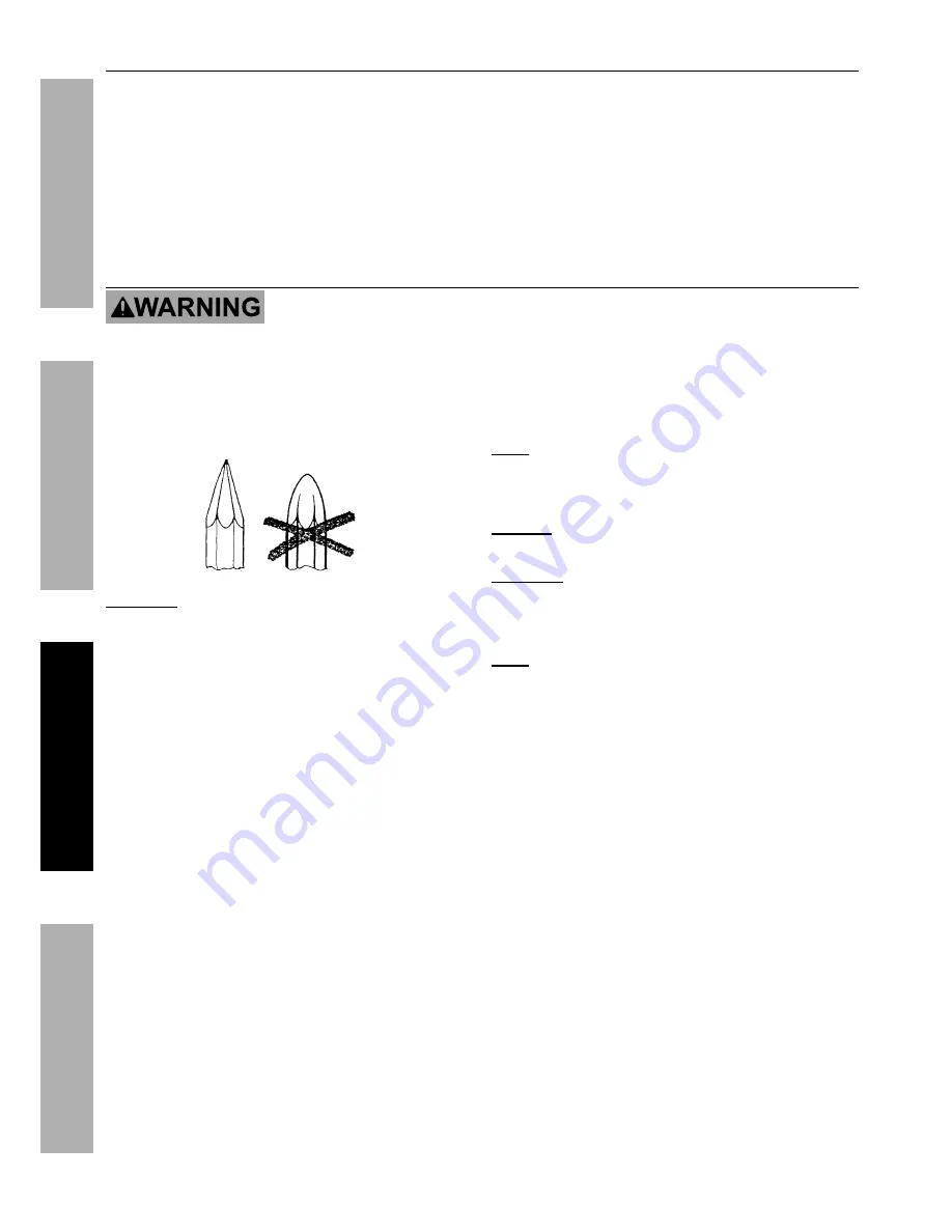
1.  Check Chisel for dullness, cracks, or other 

damage.  Sharpen or replace if necessary.

CAUTION!

 Dull tipped chisels can cause unnecessary 

chisel movement, resulting in tool wear and 

possible injury.  Use only sharp tipped chisels.

2.  Clearly mark the work area.

3.  Start the Engine as detailed in 

Starting 

the Engine

 on page 8.

4.  Grip the Handlebar of the 

Breaker Hammer with both hands.

5.  Set the bit against the work area.

6.  Press down on the Throttle. 

Note:

 Throttle does not lock.  Keep pressure 

on the Throttle to keep running the tool.

7.  Push the tool down to begin striking material.

NOTICE:

 Running tool with no load or “empty 

blows” will damage the Breaker Hammer. 

CAUTION!

 Once activated, do not press, 

bear down, or thrust forcibly against the work 

surface.  Allow the Breaker Hammer’s own 

weight to supply the needed force. 

Note:

 If the Breaker Hammer has not been used for 

a long time or is being used in low temperatures, 

the tool may require 3-5 minutes to warm up.  
8.  When work is complete, release the 

Throttle and shut off the Engine.  Refer to 

Stopping the Engine

 on page 11.

9.  Clean, then store the tool indoors 

out of children’s reach.

Содержание 61924

Страница 1: ...or month and year of purchase if product has no number Keep this manual and the receipt in a safe and dry place for future reference When unpacking make sure that the product is intact and undamaged...

Страница 2: ...ontal Single Cylinder 2 stroke Cooling System Forced air cooled Fuel Type 87 octane unleaded gasoline mixed with 2 cycle oil see below Capacity 0 45 Gallon 1 7L Oil Type 2 cycle oil designed specifica...

Страница 3: ...WARNING marking concerning Risk of Eye Injury Wear ANSI approved safety goggles with side shields Read the manual before set up and or use Symbol Property or Statement WARNING marking concerning Risk...

Страница 4: ...en transporting the equipment 8 Secure the equipment on transport vehicles to prevent it from rolling slipping and tilting 9 Industrial applications must follow OSHA requirements 10 Do not leave the e...

Страница 5: ...ent for a purpose for which it is not intended Service Precautions 1 Before service maintenance or cleaning a Turn the engine switch to its OFF position b Allow the engine to completely cool c Then re...

Страница 6: ...erforming any procedure in this section At high altitudes the engine s carburetor governor if so equipped and any other parts that control the fuel air ratio will need to be adjusted by a qualified me...

Страница 7: ...8 866 5797 For engine technical questions please call 1 800 520 0882 ITEM 61924 Safety Setup Operation Maintenance Components and Controls Handle Stop Button Air Filter Throttle Chisel Lock Muffler Ge...

Страница 8: ...mixture of unleaded gasoline and 2 cycle oil before each use 25 1 for the first 100 hours of use 30 1 thereafter Before each use check the fuel level Do not run the Engine with an improper unleaded ga...

Страница 9: ...on the Handlebar Grip the Starter Handle of the Engine loosely with the other hand and pull the handle gently until resistance is felt Allow Cable to retract fully and then pull it quickly Repeat unt...

Страница 10: ...1 Check Chisel for dullness cracks or other damage Sharpen or replace if necessary CAUTION Dull tipped chisels can cause unnecessary chisel movement resulting in tool wear and possible injury Use only...

Страница 11: ...To stop the engine in an emergency release the Throttle and press the Stop Button until the Engine stops 2 Under normal conditions use the following procedure a Release the Throttle b Let Engine idle...

Страница 12: ...tenance and Lubrication Schedule Note This maintenance schedule is intended solely as a general guide If performance decreases or if equipment operates unusually check systems immediately The maintena...

Страница 13: ...OUNCES 2 CYCLE OIL APPROVED CONTAINER First 100 hours of use 1 GALLON UNLEADED GASOLINE 4 25 FLUID OUNCES 2 CYCLE OIL APPROVED CONTAINER After 100 hours of use Figure C Gasoline Oil Mixture 4 If neede...

Страница 14: ...ound it 2 Remove the Fuel Cap from the Fuel Tank 3 Use a suction pump not included to pump any fuel in the Tank into a proper gasoline container 4 Use a piece of wire with a hook on one end to careful...

Страница 15: ...proper gasoline container c After all fuel has been removed from the tank replace the Fuel Cap and tighten securely 3 LUBRICATION a Clean out area around spark plug Remove spark plug and pour one tab...

Страница 16: ...ly tap side of carburetor float chamber with screwdriver handle 8 Turn Choke to RUN position Remove spark plug and pull the start handle several times to air out the chamber Reinstall spark plug and s...

Страница 17: ...ed technician service magneto 4 Secure spark plug cap Engine stops when under heavy load 1 Dirty air filter 2 Engine running cold 1 Clean or replace element 2 Allow engine to warm up prior to operatin...

Страница 18: ...THERETO OR ARISING OUT OF HIS OR HER INSTALLATION OF REPLACEMENT PARTS THERETO Engine Parts List Part Description Qty 1 Ring 1 2 Start Handle 1 3 Screw M5x20 11 4 Elastic Washer 5 21 5 Washer 5 21 6...

Страница 19: ...1 800 520 0882 ITEM 61924 Safety Setup Operation Maintenance Engine Assembly Diagram 1 2 3 4 5 6 7 8 9 10 11 12 13 14 15 16 17 18 19 20 21 22 23 24 25 23 26 27 28 29 29 30 32 33 4 5 34 35 17 36 37 38...

Страница 20: ...clip 40 1 83 Circlip 17 1 84 Eccentric Wheel Series 1 85 Bearing 6204 P5 1 86 Bearing Plate 1 87 Bolt M5x10 4 88 Large Gear 1 89 Bearing 6202 P5 1 90 Inflating Plate 1 91 Bearing 6205 P5 1 92 Eccentri...

Страница 21: ...520 0882 ITEM 61924 Safety Setup Operation Maintenance Machine Assembly Diagram 63 64 65 66 63 67 68 69 70 71 72 73 74 75 76 77 78 69 79 80 81 79 82 83 84 85 86 88 87 89 90 91 92 93 94 95 63 98 97 96...

Страница 22: ...sing from the use of our product Some states do not allow the exclusion or limitation of incidental or consequential damages so the above limitation of exclusion may not apply to you THIS WARRANTY IS...

Страница 23: ...l purchaser and each subsequent purchaser that the engine is free from defects in materials and workmanship that cause the failure of warranted parts for a period of two 2 years after the date of deli...

Страница 24: ...3491 Mission Oaks Blvd PO Box 6009 Camarillo CA 93011 1 888 866 5797...

Отзывы: