background image

21. REMOVE FOREIGN OBJECTS FORM STOCK. All nails, screws, and all other hardware

must be removed from wood before planing. Never allow planer to come in contact with any
metal when operating. This will chip the blades.

22. DO NOT LEAVE BLADE EXPOSED WHEN NOT IN USE. Never lay planer on its shoe

while cutter head is exposed. Retract cutter head entirely when storing.

23. DO NOT COVER OR ALLOW AIR VENTS TO BECOME BLOCKED. Motor requires

sufficient ventilation to prevent overheating.

24. KEEP ALL GUARDS IN PLACE. Do not operate if a guard is functioning improperly.

25. KEEP CHIP CHUTE CLEAR. Make sure there are no obstructions that would prevent the

ejection of chips. 

Always 

unplug tool and let cutterhead reach a complete stop before

clearing out chute.

26. RELEASE TRIGGER IMMEDIATELY AFTER REMOVING CUTTERHEAD FROM STOCK.

Do not leave trigger locked on after lifting. Only use trigger lock when planing for extended
period of time and when cutterhead will be in constant contact with your stock.

GROUNDING INSTRUCTIONS

1. This machine has a three prong plug. The third prong (round) is the ground. Plug the

machine’s cord only into three-prong receptacles. Never cut off the round prong. Cutting off
the ground will result in a safety hazard and void the warranty.

2. If a three-prong receptacle is not available, you may use an adapter. Extending from the

male end of the adapter, you will find a ring connector or wire lead with a  ring connector
where the ground (round prong) would be. Remove the center screw of the outlet cover and
put the screw through the ring connector and back into the hole of the outlet cover. Do not
over tighten or you will crack the outlet cover.

VOLTAGE WARNING

Common household current is 110-120 volts. As long as your tool is rated from 110V-120V there
will be no complications using this tool with household receptacles. If your tool is rated 220V-240V
it has a completely different style of plug and must be used with a 220V-240V receptacle. Never try
to plug a 110V-120V tool into a 220V-240V circuit (or vice-versa) or serious complications will
arise, including possible injury to the operator. The plugs and receptacle have completely different
shapes to prevent this from occurring accidentally. Do not modify your plug in any way. If you have
any doubts, call a qualified electrician.

Page 4 -- SKU: 32222

Содержание 32222

Страница 1: ... reserved No portion of this manual or any artwork contained herein may be reproduced in any shape or form without the express written consent of Harbor Freight Tools For technical questions and replacement parts please call 1 800 444 3353 Due to continuing improvements actual product may differ slightly from the product described herein ...

Страница 2: ...ns Don t expose to rain Keep work area well lit Do not use electrically powered tools in the presence of flammable gases or liquids 3 KEEP CHILDREN AWAY Children must never be allowed in the work area Do not let them handle machines tools or extension cords 4 STORE IDLE EQUIPMENT When not in use tools must be locked up in a dry location to inhibit rust Always lock up tools and keep out of reach of...

Страница 3: ...th your finger on the trigger whether it is plugged in or not 15 OUTDOOR EXTENSIONS CORDS When the equipment is operated outdoors use only extension cords intended or outside use See chart under Extension Cords for the proper AWG rating depending on the length of the cord s being used 16 STAY ALERT Watch what you are doing use common sense Do not operate any tool when you are tired 17 CHECK DAMAGE...

Страница 4: ... prong round is the ground Plug the machine s cord only into three prong receptacles Never cut off the round prong Cutting off the ground will result in a safety hazard and void the warranty 2 If a three prong receptacle is not available you may use an adapter Extending from the male end of the adapter you will find a ring connector or wire lead with a ring connector where the ground round prong w...

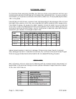
Страница 5: ...hat AWG rating is required for your situation Cord length is rated in feet AMP TOTAL EXTENSION CORD S LENGTH IN FEET RATING 25 50 75 100 125 150 175 200 0 10 0 18 18 16 16 14 14 12 12 A 10 1 13 0 16 16 14 14 14 12 12 12 W 13 1 15 14 14 12 12 12 12 12 __ G 15 18 14 12 12 12 12 12 __ __ Always inspect extension cords for any damage If there are any loose frayed or exposed wires damaged insulation or...

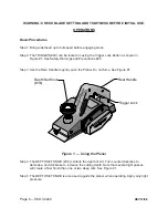
Страница 6: ...gure 1 Depth Set Knob 36 Rear Handle Trigger Lock Figure 1 Using the Planer Step 4 The DEPTH SET KNOB 36 controls the depth of cut Turn counterclockwise to decrease and clockwise to increase the cutting depth Note that several light passes will create a finer finish than one or two deep cuts See Figure 1 Step 5 The DEPTH SET KNOB is also used to guide the planer when operating Apply only light pre...

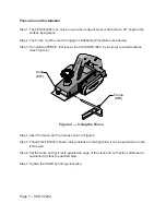
Страница 7: ...nt KNOB 61 by turning it counterclockwise See Figure 2 Knob 61 Fence 65 Step 4 Insert the fence into the hole as shown in Figure 2 Step 5 Though the FENCE is shown being installed in the right side it can be positioned on the left as well Step 6 Set the fence so that it rests against the edge of the stock and so that the cutterhead is positioned to plane the desired area Step 7 Tighten the KNOB by...

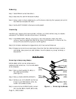
Страница 8: ...groove must fit together Step 2 Do not allow cutterhead to engage stock until it has reached full speed Step 3 Engage motor and move planer slowly forward so that the cutterhead begins to plane Use slightly more pressure on both handles move the planer very slowly and keep a steady hand MAINTENANCE Removing Sharpening Blades Both BLADES 19 must be sharpened or replaced at the same time To remove B...

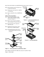
Страница 9: ... on the front of the JIG Step 3 Set the BACK PLATE against the back of the JIG Step 4 Holding both pieces firmly in place tighten the two SCREWS 24 Step 5 Snap blade assembly back into the CUTTER BLOCK 16 as shown in Figure 6 Figure 6 Placing the Blade onto the Cutter Block Step 6 Replace the BLADE HOLDER 21 using the three BOLTS 23 Sharpening Angle Blade 19 Sharpening Jig 63 Screw 24 Blade 19 Bac...

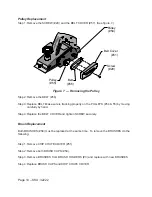
Страница 10: ...ng properly on the PULLEYS 54 55 by moving carefully by hand Step 4 Replace the BELT COVER and tighten SCREW securely Brush Replacement Both BRUSHES 58 must be replaced at the same time To remove the BRUSHES do the following Step 1 Remove CHIP CHUTE COVER 51 Step 2 Remove both BRUSH CAPS 59 Step 3 Remove BRUSHES from BRUSH HOLDERS 3 and replace with new BRUSHES Step 4 Replace BRUSH CAPS and CHIP C...

Страница 11: ...ervicing Planer starts but cutterhead Worn or broken belt Replace belt does not move Planer starts cutterhead moves Blade not extended beyond foot Adjust for more cutting but wood remains uncut depth Belt worn and slipping Replace belt Operation interrupted Forcing Unit Apply less pressure Overloaded circuit Use on an isolated circuit Check for adequate amp rating and if necessary install proper f...

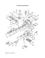
Страница 12: ...ew 30 Washer 32 Front Foot 33 Rubber Packing 34 Spring 35 Washer 36 Depth Set Knob 37 Scale 38 Washer NO DESCRIPTION 39 Thrust Washer 40 Trigger Switch 41 Noise Suppresser 42 Terminal 43 Cord Assembly 44 Cord Strain Relief 45 Cord Clip 46 Internal Wire Assembly 47 Connector 48 Tapping Screw 49 Plate 50 Rear Foot 51 Handle 52 Chip Chute Cover 53 Tapping Screw 54 Pulley A 55 Pulley B 56 Belt 57 Belt...

Страница 13: ...EXPLODED VIEW DRAWING Page 13 SKU 32222 ...

Отзывы: