background image

RM43596 JBOD 


/ System Components Removal and Installation


 22 


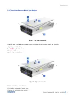
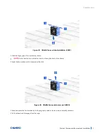
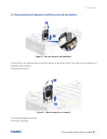
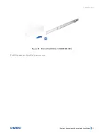
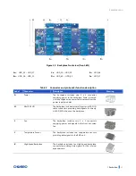
Figure 19    Middle fan modules Installation (8038) 


1. Hold the finger grips of fan brackets as shown. 


NOTE:


Ensure that the arrow sticker on the fan is facing the back of the chassis. 

2. Insert the fan module until it is secured with a click. 


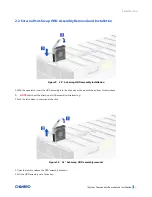
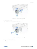
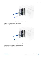
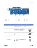
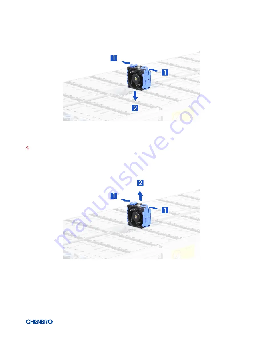
Figure 20    Middle fan modules removal (8038) 


1. Grasp and press the fan brackets by the finger grips to release the fan module vertically as shown. 

2. Pull it outward and disengage from fan cage.   


Содержание 387-43596-3300A0

Страница 1: ...RM43596 JBOD Rackmount Chassis User Manual January 2019 Version 1 0 A document provides an overview of product features functions architecture and support specifications...

Страница 2: ...or usage in trade This document contains information on products services and or processes in development All information provided here is subject to change without notice Contact your Chenbro repres...

Страница 3: ...4 2 System Components Removal and Installation 15 2 1 Top Cover Removal and Installation 16 2 2 External Hot Swap HDD Assembly Removal and Installation 17 2 3 System Maintenance 19 2 4 Fan Module Remo...

Страница 4: ...le installation 8038 20 Figure 17 Front fan module removal 8038 21 Figure 18 Front fan module removal 8038 21 Figure 19 Middle fan modules Installation 8038 22 Figure 20 Middle fan modules removal 803...

Страница 5: ...tem environmental specifications summary 13 Table 5 System packaging information 14 Table 6 Product weight information 14 Table 7 Drive power LED activity LED behavior 29 Table 8 Backplane specificati...

Страница 6: ...Card with Console Debug Power Supply 1 1 CRPS 80 Plus Platinum 2000W Default 185mm x 73mm x 40mm D x W x H Indicator Front 1 x Power Status 1 x UID 1 x HDD Activity 1 x Global Failure 1 x LCM Rear 1...

Страница 7: ...1 System Features Overview Figure 1 Overview Figure 2 Overview A Rack Handle B LCM Display C Top Cover Latch D Front Control Panel E 3 5 Storage Drive Bay F Front Hot Swap Fan Module G Middle Fixed Fa...

Страница 8: ...RM43596 JBOD Product Overview 8 1 2 Front Panel Figure 3 Front panel A Rack Handles B Front Control Panel C LCM Display D Front Hot Swap Fan Module...

Страница 9: ...RM43596 JBOD Product Overview 9 1 3 Back Panel Figure 4 Back panel overview A External Expander Cards B CRPS PSU C Rear Hot Swap Fan Module D QIG Label E UID Button F IPMI Port G Power Button...

Страница 10: ...t Control Panel Figure 5 Front control panel Table 2 Front control panel Label ICON Indicator button or connector A UID Button LED B Power LED C System Alarm LED D HDD Activity LED E LCM Display F Pag...

Страница 11: ...RM43596 JBOD Product Overview 11 1 5 Chassis Dimensions Figure 6 Chassis dimensions...

Страница 12: ...ons Caution Exceeding the specified maximum weight limit of a given rail kit or misalignment of the server in the rack may result in failure of the rack rails causing damage to the system or personal...

Страница 13: ...y and data integrity Class 2 A second tier of performance reliability and data integrity HDD I O throughput degradation SPEC Pass Fail Criteria No functional failure during test or post test diagnosti...

Страница 14: ...or subsequent shipment Table 5 System packaging information Part Number Single Bulk Form factor mm Support level 387 43596 3300A0 Single 1209 x 639 x 120 L6 NOTE The design of the inner packaging comp...

Страница 15: ...ts for a variety of different storage option 96 x 3 5 Hot Swap SAS SATA HDD Support for different storage and peripheral options will vary depending on the system model and or available accessory opti...

Страница 16: ...s cover with the grooves on the chassis base and install the cover vertically as shown 5 guide pins for both side NOTE Keep the latch vertical 2 Press the latch to lock 3 Secure with 4 screws as shown...

Страница 17: ...ation 1 With the open latch insert the HDD assembly into the drive bay as shown until the bottom of chassis base NOTE Watch out the direction of HDD assembly while inserting 2 Push the latch when it i...

Страница 18: ...lick Figure 12 3 5 HDD removal tool less type 1 Bottom up the HDD tray as shown 2 Press your 2 thumbs on the HDD as shown NOTE Watch out the direction of HDD assembly while inserting NOTE Please opera...

Страница 19: ...nto the rack tool less type 1 Push the system all the way into the cabinet by 2 persons or more 2 Secure the system with thumb screws on both sides as shown Figure 14 Removal of whole system from the...

Страница 20: ...installation 8038 Figure 16 Front fan module installation 8038 1 Hold the finger grips of fan brackets as shown NOTE Ensure that the arrow sticker on the fan is facing the back of the chassis 2 Inser...

Страница 21: ...nt fan module removal 8038 Figure 18 Front fan module removal 8038 1 Remove the shock absorbing pads on the front fan modules 2 Grasp and press the fan brackets by the finger grips to release the fan...

Страница 22: ...ckets as shown NOTE Ensure that the arrow sticker on the fan is facing the back of the chassis 2 Insert the fan module until it is secured with a click Figure 20 Middle fan modules removal 8038 1 Gras...

Страница 23: ...odules installation 8038 1 Hold the latches of rear fan module 2 Insert the fan module to the rear fan cage until it is secured with a click Figure 22 Rear fan modules removal 8038 1 Press and hold th...

Страница 24: ...nal expander card installation 1 Align the slot of the internal expander card with the guide pin on the chassis as shown and install the card vertically until it reaches the Air Max connectors 2 Press...

Страница 25: ...nder card installation 1 Slide the external expander card into the chassis as shown 2 Secure it with a thumb screw clockwise Figure 17 External expander card removal 1 Loosen the thumb screw anti cloc...

Страница 26: ...on 1 Grasp the finger grip with your fingers except the thumbs while pressing and holding the PSU latch with 1 thumb 2 Slide into the chassis until it is secured with a click Figure 26 CRPS PSU remova...

Страница 27: ...installation 1 84H314610 003 1 Attach the inner rail to the chassis base while aligning T pins on the side of the system with the slots on the inner rail Figure 28 Slide rail installation 2 84H314610...

Страница 28: ...RM43596 JBOD System Components Removal and Installation 28 Figure 29 Slide rail installation 3 84H314610 003 4 Install the system into the rack by 2 persons or more...

Страница 29: ...D ICON LED Color Behavior Condition A Activity LED Green Stay on Access Red Solid on Failure 1Hz blink Rebuild 4Hz blink Locate B Activity LED Green 1Hz blink Access C Activity LED Red Stay on SAS sig...

Страница 30: ...S SATA SFF 8680 12Gb s rated drive interface connectors providing both power and I O signals to attached devices Hot swap support for SAS SATA devices I2C interface from a 4 pin connector for device s...

Страница 31: ...indicates Mini SAS HD Link status Access LED Green When SAS signal link is busy Error LED Red when SAS signal link is error Environment Monitor Temperature sensor Connectors 1 26 x SFF 8482 2 2 x Min...

Страница 32: ...kplane via a power cable harness from the power supply modules H Mini SAS HD The backplane includes two multi port mini SAS HD cable connectors providing data signals for twenty six SAS SATA drives on...

Страница 33: ...is error LED indicates Mini SAS HD Link status Access LED Green When SAS signal link is busy Error LED Red when SAS signal link is error Environment Monitor Temperature sensor Connectors 1 26 x SFF 84...

Страница 34: ...to the backplane via a power cable harness from the power supply modules J Mini SAS HD The backplane includes 2 multi port mini SAS HD cable connectors providing data signals for twenty four SAS SATA...

Страница 35: ...to examine the DOA products If the damage of DOA products is caused by improper action as described above the customer will be liable for paying the related charge having occurred or paying the fee o...

Отзывы: