RM43596 JBOD
/ Backplane
│
29
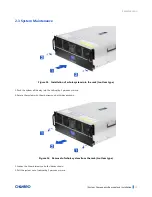
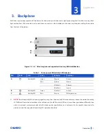
3.
Backplane
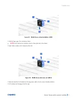
Each drive tray includes separate LED indicators for drive activity and drive status. Light pipes integrated into the drive tray direct
light emitted from LEDs mounted next to each drive connector on the backplane to the drive tray faceplate, making them visible
from the front of the system.
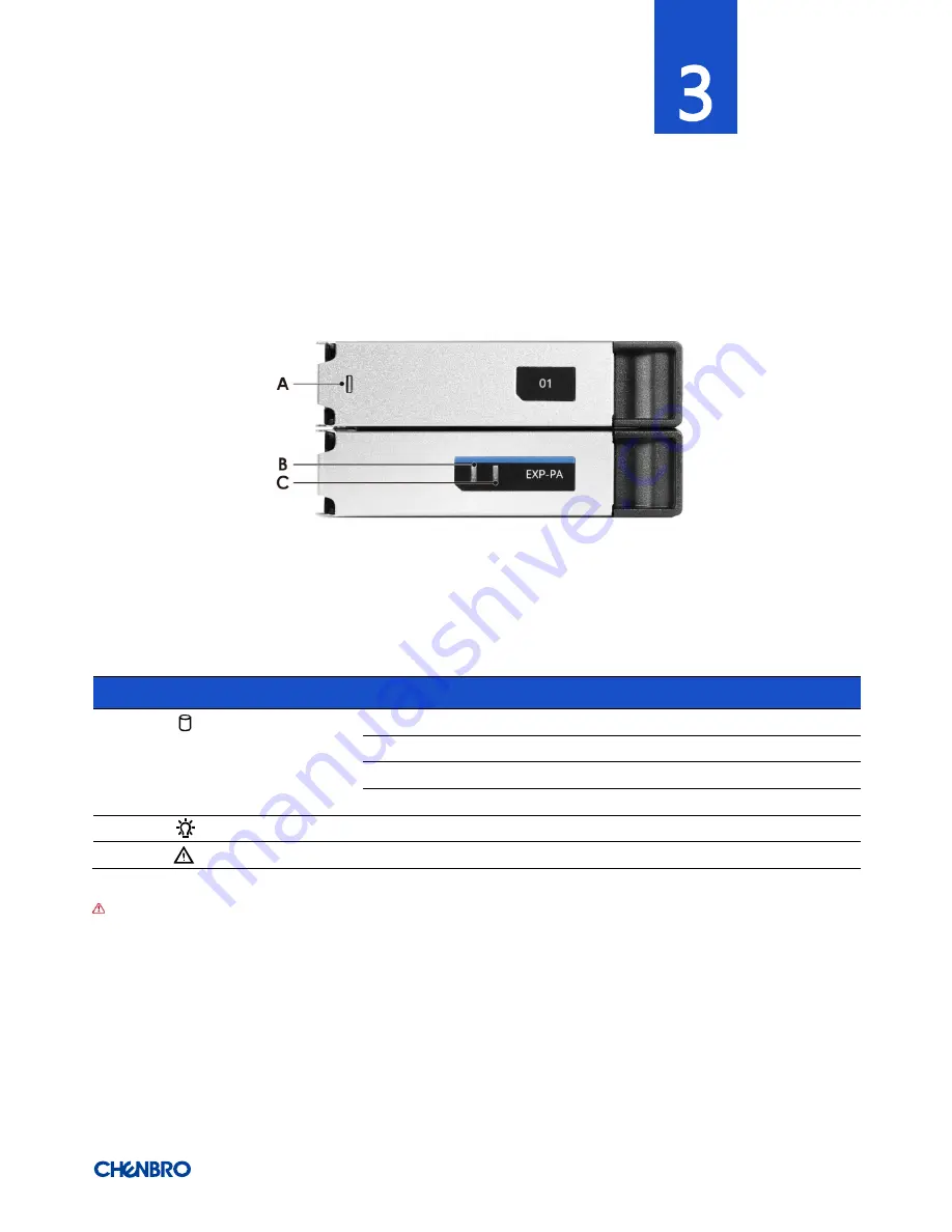
Figure 30
3.5” Drive tray/internal expander drive tray LED identification
Table 7 Drive power LED/activity LED behavior
LED
ICON
LED
Color
Behavior
Condition
A
Activity LED
Green
Stay on
Access
Red
Solid on
Failure
1Hz blink
Rebuild
4Hz blink
Locate
B
Activity LED
Green
1Hz blink
Access
C
Activity LED
Red
Stay on
SAS signal error
NOTE:
The drive activity LED is driven by signals coming from the drive itself. Drive vendors may choose to operate the activity
LED different from what is described in the table above. Should the activity LED on a given drive type behave differently than
what is described, customers should take the drive vendor specifications as a reference for the specific drive model to
determine what the expected drive activity LED operation should be.


