background image

–11 –

4.0  SELECTING THE MEASUREMENT MODE

4.1   Which mode & transducer do I use for my application? 

High penetration plastics and castings

: The most common mode for these types 

of applications is pulse-echo. Cast iron applications require 1 – 5MHz frequencies, and 
cast aluminum requires a 7 – 10MHz frequency depending on the thickness. Plastics 
typically require lower frequencies depending on the thickness and make-up of the 
material as well. Larger diameters offer greater penetration power based on the size of 
the crystal.

Corrosion & Pit Detection in steel and cast materials

: Pulse-echo mode is 

commonly used for locating pits and defects. Typically a 5MHz transducer, or higher, 
will be used for these types of applications. Use low frequencies for greater penetration 
and use higher frequencies for better resolution.

Measuring Material & Coatings

: The pulse-echo coating mode should be used 

when both material and coating thickness are required, while still requiring the ability 
to detect flaws and pits. A special coating style transducer is required for use in this 
mode. There are a variety of coating transducers in various frequencies available from 
Electromatic.

Thru Paint & Coatings

: Often times, users will be faced with applications where 

the material will be coated with paint or some other type of epoxy material. Since the 
velocity of the coating is approximately 3 times slower than that of steel, pulse-echo 
mode will result in an error if the coating or paint is not completely removed.

Thin materials

: Pulse echo mode and a high frequency transducer is commonly used 

for these types of applications. The most common transducers are the 7.5MHz and 
10MHz models with extra resolution. The higher frequencies provide greater resolution 
and a lower minimum thickness rating overall.

High temperature

: Special 5 MHz High temperature transducers are available for 

these types of applications. Both pulse-echo and echo-echo modes will also work for 
these applications. However, echo-echo mode will eliminate error caused by temperature 
variations in the transducer.

Noisy Material

: Materials such as titanium, stainless steel, and aluminum may  

have inherent surface noise issues or mirroring effect. Higher frequency transducers  
7 – 10MHz offer improved resolution to avoid erroneous measurements.

Restricted access

: Measuring materials with extreme curvatures or restricted access 

are best suited for higher frequencies and smaller diameter transducers.

Содержание TI-25PX

Страница 1: ...MODEL TI 25PX ULTRASONIC THICKNESS GAUGE Operating Manual ...

Страница 2: ...ent 8 3 1 Time versus thickness relationship 3 2 Suitability of materials 3 3 Range of measurement and accuracy 3 4 Couplant 3 5 Temperature 3 6 Measurement modes 4 0 Selecting the measurement mode 11 4 1 Which Mode and Transducer do I use for my applications 5 0 Making measurements 12 5 1 Probe Zero 5 2 Velocity Calibration 6 0 Additional features 14 6 1 Unit 6 2 Light 6 3 Lock 6 4 Factory Defaul...

Страница 3: ...y one side of the material being measured 1 1 Disclaimer Inherent in ultrasonic thickness measurement is the possibility that the instrument will use the second rather than the first echo from the back surface of the material being measured This may result in a thickness reading that is TWICE what it should be Responsibility for proper use of the instrument and recognition of this phenomenon rest ...

Страница 4: ...0 Key The PRB 0 key is used to zero the TI 25PX in much the same way that a mechanical micrometer is zeroed If the gauge is not zeroed correctly all of the measurements that the gauge makes may be in error by some fixed value Refer to section 5 1 for a further explanation of this important feature 2 3 VEL Key The VEL key is used to enter and exit the TI 25PX s calibration mode This mode is used to...

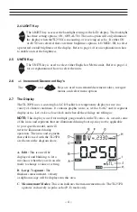
Страница 5: ... TI 25PX uses a custom glass LCD backlit low temperature display for use in a variety of climate conditions It contains graphic icons as well as both 7 and 14 segment display areas Let s take a closer look and what all these things are telling us NOTE This display is used for multiple gauge models in the TI series As a result some of the icons and segments that are illuminated during boot up may n...

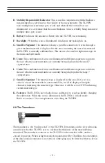
Страница 6: ...segment area I Units This combination of icons are illuminated in different sequences to inform the user what measurement units are currently being displayed in the large 7 segment area J Small 14 Segment The material type is displayed in this area If it is set to a value of one of the materials in our material list it will be displayed in alpha characters indicating the material type Otherwise it...

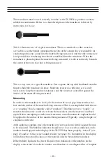
Страница 7: ...he material being measured Measuring In order for the transducer to do its job there must be no air gaps between the wear face and the surface of the material being measured This is accomplished with the use of a coupling fluid commonly called couplant This fluid serves to couple or transfer the ultrasonic sound waves from the transducer into the material and back again Before attempting to make a...

Страница 8: ...Transducer Connectors Refer to Diagram The transducer connectors and battery cover probe zero disk are located on the TI 25PX s top end cap The transducer connectors are of type Lemo 00 NOTE There is no polarity associated with connecting the transducer to the TI 25PX it can be plugged into the gauge in either direction Probe Zero Disk Battery Cover Refer to Diagram The Battery cover is the large ...

Страница 9: ...easurement is practical in a wide variety of materials including metals plastics and glass Materials that are difficult include some cast materials concrete wood fiberglass and some rubber 3 3 Range of measurement and accuracy The overall measurement capabilities based on the wide variety of materials is determined by the consistency of the material being measured The range of thickness that can b...

Страница 10: ...e to changes in the temperature of the transducer However multi echo techniques offer temperature compensation help to minimize these errors 3 6 Measurement Modes This section will cover the different measurements modes of the TI 25PX the transducers required and the reasons for using specific modes Pulse Echo P E Mode Pulse echo mode measures from the initial pulse sometimes referred to as an art...

Страница 11: ...measurements Dual element delay line transducers are have a usable range of 0 025 and up depending on the material frequency and diameter A limitation of dual element delay line transducers is the V shaped sound path Because the sound travels from one element to another the time versus thickness relationship is non linear Therefore a correction table in the instruments software is used to compensa...

Страница 12: ... frequencies available from Electromatic Thru Paint Coatings Often times users will be faced with applications where the material will be coated with paint or some other type of epoxy material Since the velocity of the coating is approximately 3 times slower than that of steel pulse echo mode will result in an error if the coating or paint is not completely removed Thin materials Pulse echo mode a...

Страница 13: ...short list of materials To select a common material type to use for calibration refer the Basic Material Type section 5 3 5 1 Probe zero Setting the zero point of the TI 25PX is important for the same reason that setting the zero on a mechanical micrometer is important It must be done prior to calibration and should be done throughout the day to account for any temperature changes in the probe If ...

Страница 14: ...ng the velocity value are outlined below 1 With the transducer free from contact with the material press the key to display the current velocity 2 Use the and keys to scroll the velocity to the known target value NOTE The longer the keys are pressed and held the faster the value will increment decrement NOTE Pressing the key prior to pressing the key will abort the cal routine without saving any c...

Страница 15: ...ressing the key will abort to the measurement screen without saving changes 3 When the desired LITE setting is displayed press the key to set the status and edit the BRT brightness option 4 Use the and keys to scroll through the BRT LO MED HI options 5 When the desired BRT setting is displayed press the key to set the brightness and return to the measurement screen 6 3 Lock The lock feature was bu...

Страница 16: ...the TI 25PX on 6 8 Factory Defaults The TI 25PX can be reset to factory defaults at any time to restore the original gauge settings This should only be used if the gauge is not functioning properly or perhaps multiple features have been enabled and a clean start is needed The procedure to reset the gauge is outlined below 1 With the TI 25PX powered off press and hold down the and keys while poweri...

Страница 17: ...0 0850 2159 Magnesium 0 2300 5842 Mercury 0 0570 1448 Molybdenum 0 2460 6248 Monel 0 2110 5359 Nickel 0 2220 5639 Nylon 0 1060 approx 2692 Platinum 0 1560 3962 Plexiglas 0 1060 2692 Polystyrene 0 0920 2337 PVC 0 0940 2388 Quartz glass 0 2260 5740 Rubber vulcanized 0 0910 2311 Silver 0 1420 3607 Steel 1020 0 2320 5893 Steel 4340 0 2330 5918 Teflon 0 0540 1372 Tim 0 1310 3327 Titanium 0 2400 6096 Tu...

Страница 18: ...ound velocity of the material being measured starts to have a noticeable effect upon ultrasonic measurement At such elevated temperatures it is recommended that the user perform calibration on a sample piece of known thickness which is at or near the temperature of the material to be measured This will allow the TI 25PX to correctly calculate the velocity of sound through the hot material Expansio...

Страница 19: ...easuring laminates is that many included air gaps or pockets which will cause an early reflection of the ultrasound beam This effect will be noticed as a sudden decrease in thickness in an otherwise regular surface While this may impede accurate measurement of total material thickness it does provide the user with positive indication of air gaps in the laminate Measuring through paint coatings Mea...

Страница 20: ...E RESULTING FROM THE USE OF SUPPLIED EQUIPMENT WHETHER SUCH DAMAGE OCCURS OR IS DISCOVERED BEFORE UPON OR AFTER REPLACEMENT OR REPAIR AND WHETHER OR NOT SUCH DAMAGE IS CAUSED BY MANUFACTURER S OR SUPPLIER S NEGLIGENCE WITHIN ONE YEAR FROM INVOICE DATE Some State jurisdictions or States do not allow the exclusion or limitation of incidental or consequential damages so the above limitation may not a...

Страница 21: ... 20 9 0 NOTES ...

Страница 22: ......

Отзывы: