background image


Stage Designer™ 50 

Rev. 9 

1.


B

EFORE 

Y

OU 

B

EGIN


What is included 


1 x Stage Designer™ 50 


1 x DC 12 V, 500 mA output, 100~240 V, 50/60 Hz input auto-ranging  power supply 


1 x User Manual 


1 x Warranty Card 

Unpacking Instructions 

Immediately upon receiving a fixture, carefully unpack the carton, check the contents to ensure that all parts are 

present, and have been received in good condition. Notify the shipper immediately and retain packing material 

for inspection if any parts appear damaged from shipping or the carton itself shows signs of mishandling. Save 

the carton and all packing materials. In the event that a fixture must be returned to the factory, it is important 

that the fixture be returned in the original factory box and packing. 

Manual Conventions 

CHAUVET® manuals use the following conventions to differentiate certain types of information from the regular 

text. 

C

ONVENTION


M

EANING


[10] 

A DIP switch to be configured  

<Menu> 

A key to be pressed on the fixture’s control panel 

1~512 

A range of values 

50/60 

A set of values of which only one can be chosen 

Settings 

A menu option not to be modified (for example, showing the operating 
mode/current status) 

MENU >


Settings


A sequence of menu options to be followed 

ON 

A value to be entered or selected 

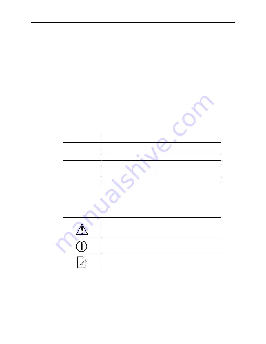
Icons 

This manual uses the following icons to indicate information that requires special attention on the part of the 

user. 

I

CONS


M

EANING


This paragraph contains critical installation, configuration or operation 
information. Failure to comply with this information may render the fixture 
partially or completely inoperative, cause damage to the fixture or cause 
harm to the user. 


This paragraph contains important installation or configuration information. 
Failure to comply with this information may prevent the fixture from 
functioning correctly. 


This paragraph reminds you of useful, although not critical, information. 


Содержание Stage Designer

Страница 1: ...User Manual ...

Страница 2: ...ng 10 ENTERING RECORD MODE RECORD ENABLE 10 CREATE A SCENE 10 EDIT ENABLE 10 ERASE A PROGRAM 11 ERASE ALL SCENES 11 RECORD CLEAR 11 DELETE A STEP OR STEPS 12 INSERT A STEP OR STEPS 12 MODIFY A STEP OR STEPS 12 5 Playback 13 PLAYING A SCENE 13 PLAYING A SCENE WITH AUDIO TRIGGERING 13 PLAYING A SCENE WITH THE SPEED SLIDER 13 PLAYING A SCENE WITH THE STANDARD BEAT 14 CHANGE THE SPEED MODE BETWEEN 5 1...

Страница 3: ...s of information from the regular text CONVENTION MEANING 10 A DIP switch to be configured Menu A key to be pressed on the fixture s control panel 1 512 A range of values 50 60 A set of values of which only one can be chosen Settings A menu option not to be modified for example showing the operating mode current status MENU Settings A sequence of menu options to be followed ON A value to be entere...

Страница 4: ... 50 is a universal intelligent lighting controller It allows the control of 48 channels with 96 scene chase playback faders Each scene chase can contain up to 1000 individual steps or looks On the surface when in the CHASE SCENE mode there are 12 physical faders for the playback of the saved programs There are 4 pages of Scenes playback on Page A and an additional 4 pages of playback faders on Pag...

Страница 5: ...Stage Designer 50 5 Rev 9 Product Overview front 21 2 5 7 8 15 12 6 4 13 1 20 3 16 10 9 18 11 19 22 23 24 25 26 27 28 29 30 31 32 14 ...

Страница 6: ...sync of chase Page A_B switches the channel faders BETWEEN 1 24 MODE AND 25 48 MODE Press and hold Record Page A_B to switch between the 2 channel pages 16 Blind Takes the channel out of a program temporarily in Chase Scene mode 17 Chase Rev Reverses the direction of the chase playback 18 Dark Used to temporarily blackout overall output 19 Home Used to deactivate the Blind on a given channel 20 Pa...

Страница 7: ...olarity 4 MIDI Thru MIDI port for connecting to a sequencer or MIDI device 5 MIDI Out MIDI port for connecting to a sequencer or MIDI device 6 MIDI In MIDI port for connecting to a sequencer or MIDI device 7 Audio Input This jack accepts a line level audio input signal ranging from 100mV to 1Vpp 8 Remote Input Blackout and Full On may be controlled by a remote control using a standard jack 9 DC In...

Страница 8: ...h a pan and tilt mirror however DMX controllers can use this term to control any DMX 512 compatible device as a generic fixture MIDI is a standard for representing musical information in a digital format A MIDI input would provide external triggering of scenes using midi devices such as a midi keyboard Stand Alone refers to a fixture s ability to function independently of an external controller an...

Страница 9: ... output to 4 While holding Record press the Flash button corresponding to the DMX output that you wish to assign the Fader to 5 Repeat steps 2 3 as often as necessary 6 Press and hold Record Rec Exit to exit the mode For example you wish to assign Fader 1 to output to DMX channel 5 1 Hold the Record button press Fader 6 3 times 2 Press the Flash button 1 3 While holding the Record button press the...

Страница 10: ...er to store your scene Tap the Page button to select a page 1 4 8 Press and hold the Record button tap the Flash button for the scene that you wish to store it to All LEDs will flash indicating the scene has been programmed into memory 9 You can continue programming or exit To exit program mode press and hold the Record button tap the Rec Exit button Notes Deselect Blackout if LED is lit Be sure t...

Страница 11: ...e the Record button 4 All LEDs should light indicating all programs have been erased 5 Press and hold RECORD REC EXIT to exit the mode Notes You must be in Record mode to Reset the controller The LED over the Record button will light indicating the Record mode operation Warning this will reset the controller to its factory defaults This will erase all programs and settings Record Clear Action 1 Re...

Страница 12: ... of entering the Edit enable is selecting which scene you wish to Edit See section on Edit enable for further instructions All LEDs will flash to indicate a successful Insert of the step Modify a Step or Steps Action 1 Edit enable 2 Press and hold the Up button if you want to raise the intensity Press the Down button if you want to lower the intensity 3 Tap the Step button to scroll to the step wh...

Страница 13: ...s the Chase Scene Yellow is 2 scene preset A B And Green is 1 24 single mode You may press and hold down the relevant Flash button for the Scene to trigger the button momentarily Playing a Scene with Audio Triggering Action 1 Select your Scene as described in the above section 2 Tap the Audio button until its LED lights indicating AUDIO mode is active 3 Use the Audio Level slider to adjust the sen...

Страница 14: ...d to these functions such as Pan tilt control very useful for remote followspot controls Action 1 Press hold RECORD tap the Flash button 7 or 8 3 times The display should indicate activation of the mode 2 There are 3 functions FUNC 1 states that the Auxiliary control is not assigned to any channel FUNC 2 refers o the auxiliary controls working much like the channel fader along with the flash butto...

Страница 15: ...to exit MIDI setting Notes This is the Channel that the controller will receive MIDI note commands MIDI NOTE FUNCTION TURN ON OFF 22 69 Trigger scenes 1 48 100 70 117 Activate Channel 1 48 118 FULL ON 119 DARK momentary blackout 120 HOLD 121 Turn on or off AUDIO 122 MODE CHASE SCENE 123 MODE 1 12A_1 12B 124 MODE 1 24A 125 Step 126 BLACKOUT 127 Channel page 1 24 25 48 Setting MIDI OUT Action 1 Whil...

Страница 16: ...sfer During FILE DUMP all other operations will cease to function If errors or power failure occurs FILE DUMP will be interrupted and stop Action 1 While holding down the RECORD button simultaneously tap Flash button 4 three times The display reads MIDI FILEDUMP SENDING 000 when the device is in the correct mode 2 While holding down RECORD tap the REC EXIT button to exit MIDI setting Notes This is...

Страница 17: ... 4 RMA 5 A brief description of the cause for the return Claims Damage incurred in shipping is the responsibility of the shipper therefore the damage must be reported to the carrier upon receipt of merchandise It is the customer s responsibility to notify and submit claims with the shipper in the event that a fixture is damaged due to shipping Any other claim for items such as missing component pa...

Страница 18: ... 0 5 A 250 V THERMAL Maximum ambient temperature 104 F 40 C CONTROL PROGRAMMING 3 pin DMX Data output locking 3 pin XLR female socket Data pin configuration pin 1 shield pin 2 pin 3 Protocols DMX 512 USITT 5 pin DMX Data output locking 5 pin XLR female socket Data pin configuration pin 1 shield pin 2 pin 3 pins 4 5 not used Protocols DMX 512 USITT ORDERING INFORMATION Stage Designer 50 STAGEDESIGN...

Отзывы: