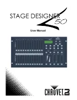
Stage Designer™ 50
13
Rev. 9
3.
O
PERATING
I
NSTRUCTIONS
Setup
Setting up the System
1.
Place the Stage Designer 50™ on a level surface. Note! The Stage Designer 50™can also be rack
mounted, occupying six rack spaces (6U).
2.
Plug the AC to DC power supply into the system back panel and into the mains outlet.
3.
Plug in your DMX cable(s) to your intelligent lighting as described in the respective fixture’s manual. For a
quick overview of DMX see the “DMX Primer” on page 19.
4.
Reset the system using the instructions on page 11 under
ERASE ALL SCENES
.
Physical Fader Assignment (optional setup)
Use this feature to combine or unify fixture control attributes for different fixtures. For example; if you were
controlling 4 moving mirrors and 4 moving yokes, the color, gobo and dimmer channels may not line up ideally
on the physical faders. Use this function to re-assign the dimmer, color and gobo channels to faders 1, 2 and 3.
From now on you will be able to control the same attributes on all fixtures using the same fader location. This is
also most useful when needing to combine all colors together.
Action
·
1.
Press and hold
RECORD
button.
2.
While holding the Record button, press the
Flash button #6 (3) times.
3.
Press the Flash button that you wish to
assign the DMX channel output to.
4.
While holding Record, press the Flash
button corresponding to the DMX output
that you wish to assign the Fader to.
5.
Repeat steps 2 to 3 as often as necessary.
6.
Press and hold Record & Rec Exit to exit
the mode.
For example: you wish to assign Fader #1 to
output to DMX channel #5.
1.
Hold the Record button & press Fader#6 (3)
times.
2.
Press the Flash button #1.
3.
While holding the Record button, press the
Flash button #5.
Notes
¥
All physical faders can be re-assigned to output
on a different DMX channel. Faders are given a
channel number and are labeled on the surface
of the controller as such.
You can check to see what the assignment is by
pressing the Fader button of the corresponding
channel while in this mode.
Here is no limit to the amount of channels that
can be assigned to a single fades. One can
assign up to all 48 channels of DMX output to a
single Fader.
CHNO corresponds to the Physical Fader, while
SLDNO corresponds to the DMX output channel.
Switching Between Page A and Page B (channels 1-24 and 25-48)
Action
·
1.
Press and hold
Record
& press
Page A_B
button. If you are on Page A, then this will
bring you to Page B. If you are on Page B,
then this will bring you to Page A.
Notes
¥
When the fixture turns on, it will revert to the
previously used page.
Page A is used to control channels 1-24, while
Page B is used to control channels 25-48.
The screen will display which current page.
There’s an additional set of 4 pages of playback
controls on Page B.
Содержание Stage Designer 50
Страница 1: ...User Manual ...


