background image


ILS-606 & ILS-625 User Manual 


2005-03-09/22:45


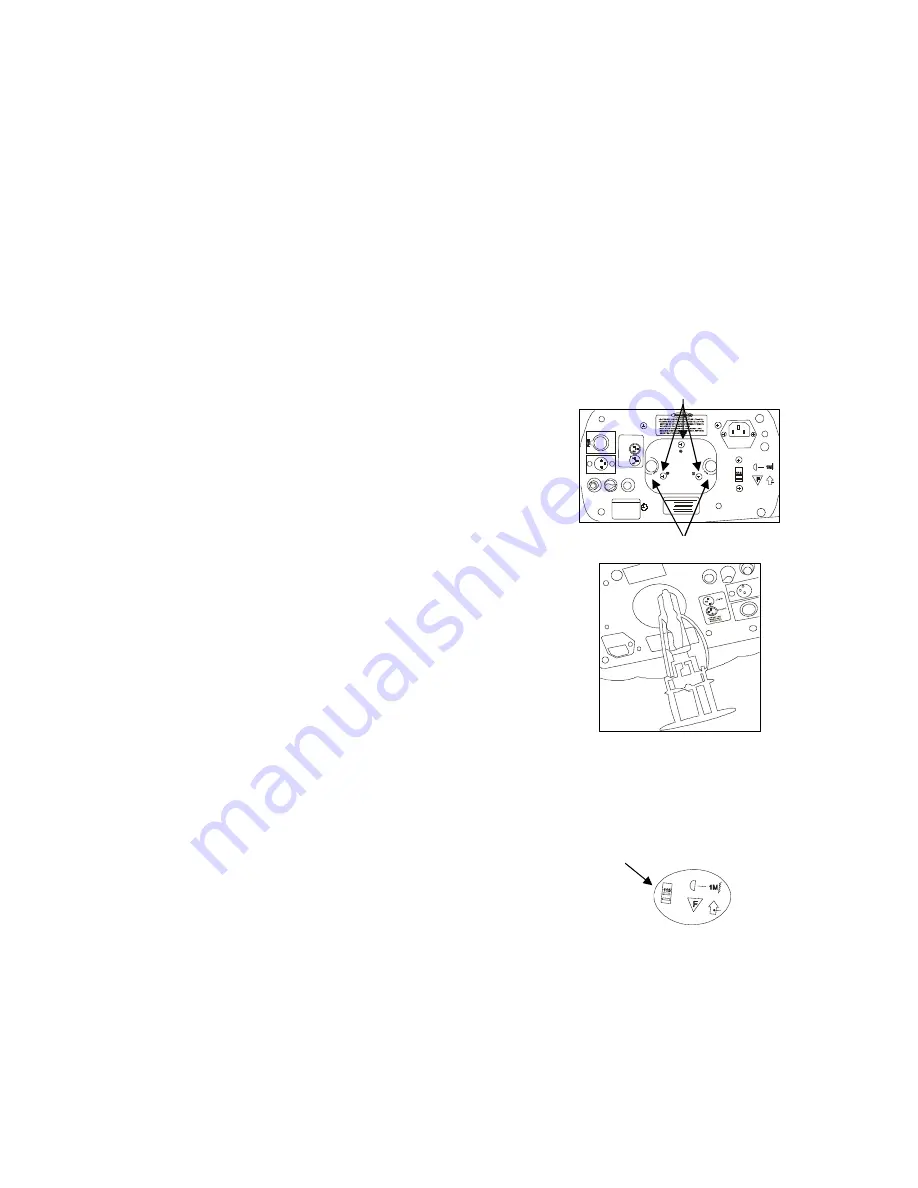
Remove both thumbscrews 

ILS-6xx Lamp Installation 

Lamp alignment screws 

O U T P UT

IN P UT

PI N1 - C O M M

PI N2 - D M X       -
PI N3 - D M X      +

M I C

S EN SI T I VI T Y

            O NL Y F O R 
RE M O T E  C O NT RO L

CO NF I G UR AT I O N
CH 1= PA N

CH 2= T IL T  RO TA T I ON
CH 3= S HU T TE R / S HA K I NG

CH 4= G OB O
CH 5= CO LO R
CH 6= G OB O  R O TA T IO N

CH 7= DI M M E R

P O WE R

F U SE


Q

C

P

A

S

S

E

D

M od el :

S er ia l  No :
P ow er :
F us e :

B ul b :

D is c o n n e c t  p o w e r  a n d  w a i t  5  m in . b e f o r e  o p e n in g .

A d ju s t  la m p  p o s it i o n  b y  tu r n i n g  s c r e w s  A , B  a n d  C .

Slide switch up or down 

depending on your line voltage. 

S

ETUP


Lamp 

You will need to install a lamp prior to the initial operation of the fixture. A MSD250 high intensity discharge 

lamp is included.  

Warning! 

When replacing the lamp, please wait 15 minutes after powering down to allow the 
unit to cool down! Always disconnect from main power prior to lamp replacement. 


Do not touch the envelope (glass area) of the bulb with bare hands. If this happens, clean the lamp with 

alcohol and wipe it with a lint free cloth before installation. 

L AM P   I NS T AL L AT I O N 

1) 

Remove both thumbscrews located on the bottom of the 
fixture. 

2) 

Pull out lamp socket plate as pictured to the right.  

3) 

If replacing the lamp, remove old lamp first. 

4) 

Holding the new lamp by its base, align the small pin on the 
lamp with the small hole in the socket and insert the lamp 
squarely until the retaining clips on the lamp socket secures 
the lamp tightly. 

5) 

Clean the glass/envelope of the bulb with an alcohol wipe 
or equivalent.  

6) 

Holding the lamp socket plate, insert the tip of the lamp into 
the fixture with extreme care. Navigate the lamp all the way 
until it reaches the reflector and the lamp base plate 
touches the bottom plate of the fixture. 

7) 

Align the screw holes and fasten the thumbscrews back 
onto the lamp socket plate. 

8) 

If you are replacing the lamp, you may want to log the 
fixture hours in order to track the lamps use. Navigate to the 
{FhrS} on the menu display to obtain this information. 

9) 

Turn the fixture on and adjust the lamp alignment screws 
until the brightest most even area of the beam is in the 
center of your spot. It may be necessary for you to use a 
controller in order to command the fixture to display a white 
beam on a flat surface with no gobos or colors.  

Power 

Your product is equipped with switch-selectable AC power setting. 


Warning! 

Verify that the power select switch on your unit 
matches the line voltage applied. All fixtures must 
be connected to circuits with a suitable Earth 
Ground.  

  To determine the power requirements for a particular fixture, 

see the label affixed to the back plate of the fixture or refer to the fixture

s specifications chart. 


  A fixture

s listed current rating is its average current draw under normal conditions. 


  All fixtures must be powered directly off a switched circuit and cannot be run off a rheostat 

(variable resistor) or dimmer circuit, even if the rheostat or dimmer channel is used solely for a 0% 
to 100% switch.  

  Before applying power to a fixture, check that the source voltage matches the fixture

requirement.  

  All fixtures must be connected to circuits with a suitable Earth Ground.  

Содержание ILS-606DBR

Страница 1: ... 800 762 1084 954 929 1115 FAX 954 929 5560 www chauvetlighting com 2005 03 09 22 45 ILS 606DBR ILS 606DSR ILS 625DCR USER MANUAL This manual includes instructions and overview on the following 3 CHAUVET products ILS 606DBR ILS 606DSR and ILS 625DCR ...

Страница 2: ... 9 Setting the starting address 10 Master Slave settings SLNd SL 1 SL 2 10 Setting the alternate slave mode SL 2 10 User Configurations CLNd IPan ItLt Irot 606DBR IdIN 11 Color Mode CLNd 11 Pan Invert IPan tilt Invert ItLt Irot 11 Segment Display Configurations Led IdSP 11 Turning the Display off Led 11 Display Inverse IdSP 11 Fixture Test and Service Functions FAdJ teSt FhrS rSet 12 Focus Adjustm...

Страница 3: ... circuits with a suitable Earth Ground Safety Instructions Please keep this User Guide for future consultation If you sell the unit to another user be sure that they also receive this instruction booklet Always make sure that you are connecting to the proper voltage and that the line voltage you are connecting to is not higher than that stated on decal or rear panel of the fixture This product is ...

Страница 4: ...06DSR Tilt 2 Gobos 3 Shutter 3 Color 4 Gobos 4 Gobo Rotation 5 Color 5 Dimmer 6 Gobo Rotation 7 Dimmer What is ILS ILS stands for Integrated Lighting System CHAUVET fixtures with the ILS logo are equipped with an advanced independent show technology that enables synchronization across all intelligent lighting fixtures within the group Gobos colors and chases are among the various features that syn...

Страница 5: ...s in the Master operating mode Slave On Unit is in the Slave operating mode Sound Flashing Sound Active mode is on SEGMENT BUTTONS I O PANEL OVERVIEW BUTTONS I O PANEL MENU Toggles programming functions DMX Out In DMX 512 connectors DOWN Steps backward through menu functions MIC Built in microphone UP Steps forward through menu functions Sensitivity POT Sets audio sensitivity ENTER Confirms select...

Страница 6: ...lean the glass envelope of the bulb with an alcohol wipe or equivalent 6 Holding the lamp socket plate insert the tip of the lamp into the fixture with extreme care Navigate the lamp all the way until it reaches the reflector and the lamp base plate touches the bottom plate of the fixture 7 Align the screw holes and fasten the thumbscrews back onto the lamp socket plate 8 If you are replacing the ...

Страница 7: ...th knobs and tilting the fixture After finding the desired position retighten both knobs When selecting installation location take into consideration lamp replacement access and routine maintenance Safety cables should always be used Never mount in places where the fixture will be exposed to rain high humidity extreme temperature changes or restricted ventilation Lamp Alignment LAMP ALIGNMENT HOW ...

Страница 8: ...mmer Inverse OPERATING INSTRUCTIONS Menu Navigation To select any of the pre set functions press the MENU button until the desired function is shown on the display Select the function by pressing the ENTER button and the display will blink Use the DOWN and UP button to change the settings Once the required setting has been selected press the ENTER button to activate it If you don not press the ENT...

Страница 9: ...ber is pre fixed by the letters ILS Master Slave operation does not require any menu or setting selections Simply connect each fixture in a daisy like fashion using qualified 3 pin DMX cables as described below The first unit in the chain will operate in a Stand Alone mode and all units following will synchronize to the first unit 1 Connect the male 3 pin connector side of the DMX cable to the out...

Страница 10: ...elect DMX addressing Once selected the display will read either a 1 or any other number that may have previously been set You must make a selection within 6 seconds 3 Press the UP and DOWN buttons to increase or decrease values until the desired value is achieved 4 Press the ENTER button to activate selection Master Slave settings SLNd SL 1 SL 2 By linking the units under a master slave control mo...

Страница 11: ...of the rest You can apply a pan and tilt Invert by following these instructions 1 Tap the MENU button until the display reads IPan or ItLt 2 Press the ENTER button to select this function The selection is confirmed when the display begins to blink You must make a selection within 8 seconds 3 Press the UP and DOWN buttons to toggle between the I for inverse and no for none 4 Press the ENTER button ...

Страница 12: ... including gobo and color effects 1 Tap the MENU button until the display reads teSt 2 Press ENTER and the fixture will immediately begin to play back a test sequence Observe tentatively for any abnormalities 3 Press the MENU button to leave this mode FIXTURE RESET RSET This function will re initialize the fixture by returning all motors to its startup positions or otherwise known as home position...

Страница 13: ...c strobe 2 sync strobe 3 two light strobe LED blinks normal Sound Fixture 606DBR 606DSR X Y moving patterns 12 patterns user selectable Fixture 625DCR Chase Pattern selection 6 patterns LED on Slow Sound Fixture All Color Gobo selection Hold for gobo change tap for color change BLACKOUT LED blinks fast Position Fixture 606DBR 606DSR X Y moving position dimmer setting Fixture 625DCR Dimmer setting ...

Страница 14: ...f one fixture connects to the DATA IN of the next fixture The order in which the fixtures are connected is not important and has no effect on how a controller communicates to each fixture Use an order that provides for the easiest and most direct cabling Connect fixtures using shielded two conductor twisted pair cable with three pin XLR male to female connectors The shield connection is pin 1 whil...

Страница 15: ...w Fast gobo scroll 5 normal 000 012 013 025 026 038 039 051 052 063 064 076 077 089 090 102 103 115 116 127 128 255 CS 000 007 008 015 016 022 023 030 031 037 038 045 046 052 053 060 061 067 068 075 076 082 083 090 091 097 098 105 106 112 113 120 121 127 128 255 Color normal Open white Green Magenta Light Blue Yellow Orange Blue UV Purple Light Green Pink Slow Fast color scroll CS color split mode...

Страница 16: ...255 CS 000 007 008 015 016 022 023 030 031 037 038 045 046 052 053 060 061 067 068 075 076 082 083 090 091 097 098 105 106 112 113 120 121 127 128 255 Color normal Open white Green Magenta Light Blue Yellow Orange Blue UV Purple Light Green Pink Slow Fast color scroll CS color split mode Open white Green Green Magenta Magenta Magenta Light Blue Light Blue Light Blue Yellow Yellow Yellow Orange Ora...

Страница 17: ... 625 User Manual 17 2005 03 09 22 45 Gobos 606DBR 606DSR Open Dots Tunnel Broken Glass Swirl Cylinder Frost Breakup Triangle 4 Dots 625 DCR Open Dots Tunnel Broken Glass Frost Cylinder Frost Breakup 3200 K 6600 K ...

Страница 18: ... the environment in which the fixture operates damp smoky or particularly dirty surrounding can cause greater accumulation of dirt on the unit s optics Clean with soft cloth using normal glass cleaning fluid Always dry the parts carefully Clean the external optics at least every 20 days Clean the internal optics at least every 30 60 days Returns Procedure Returned merchandise must be sent prepaid ...

Страница 19: ...Possible bad lamp or fixture is overheating Lamp may be at end of its life Light will not come on after power failure Some discharge lamps require a cooling off period before the electronics in the fixture can kick start it again wait 5 to 10 minutes before powering up Loss of signal Use only DMX cables Install terminator Note Keep DMX cables separated from power cables or black lights Motor movem...

Страница 20: ...OTO OPTIC Beam Angle 14 Pan ILS 606 180 Tilt ILS 606 70 THERMAL Maximum ambient temperature 40 104 F FUSE Main 20mm Glass 10A Fast Blow CONTROL PROGRAMMING Data input locking 3 pin XLR male socket Data output locking 3 pin XLR female socket Data pin configuration pin 1 shield pin 2 pin 3 Protocols DMX 512 USITT DMX Channels 606xxx 7 DMX Channels 625DCR 5 ORDERING INFORMATION Trackscan 250DBR ILS B...

Отзывы: