Charmhigh-V1.0-2016 |
14
All Rights Reserved
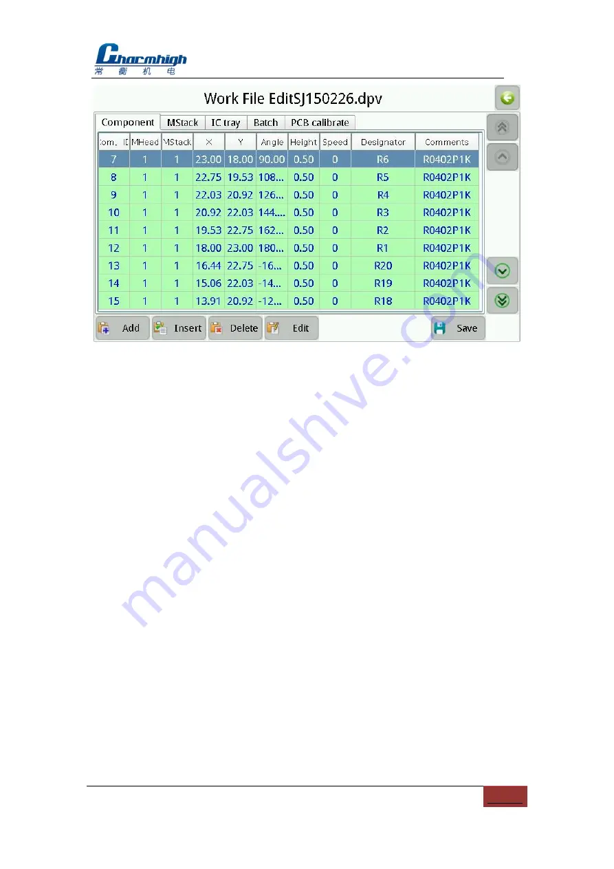
Figure.9-2
9.1.1. Component
The screen as shown above, used for managing device in PCB.
(1)
Component list:
Show all components contained in the selected work file, green
indicates enables vision calibration, orange indicates disable vacuum testing,
purple indicates enables vision calibration and disable vacuum testing, gray
indicates skip the device;
(2)
Add:
Add a component to the end of the list;
(3)
Insert:
Insert a new component before the currently selected row;
(4)
Delete:
Delete the selected component;
(5)
Edit:
To edit the selected component, see below for details;
(6)
Save:
If you edit the component in the list, the save button will flash, prompt the
information changed and has not been saved yet, click to save and stop flash.
9.1.1.1. Edit
The popup screen as shown below, the top left of the screen displays the current
component‟s line number (start from 0),the arrows on both sides, used for selecting a
component before or after, also can click the middle button popup keyboard to input
device line number directly.


