background image

5

Burner Flame Check

• Remove cooking grates and heat tents. Light burners, 

rotate knobs from 

HIGH

 to 

LOW

. You should see a 

smaller flame in

 LOW

 position than seen on 

HIGH

Perform burner flame check on side burner, also. Always 
check flame prior to each use. If only low flame is seen 
refer to "Sudden drop or low flame" in the 

Troubleshooting 

Section.

HIGH

LOW

Turning Grill Off

• Turn all knobs to the 

      OFF 

position. Turn LP cylinder 

OFF

 by turning hand-wheel clockwise to a full stop.

Ignitor Check

• Turn gas off at LP cylinder.

 Press and hold 

electronic ignitor button.  "Click" should be heard and 
spark seen each time in each collector box or 
between burner and electrode. See 

"Troubleshooting"


if no click or spark.

Valve Check

•  Important: Make sure gas is off at LP cylinder 

before checking valves

.  Knobs lock in 

OFF 

position. 

To check valves, first push in knobs and release, knobs 
should spring back. If knobs do not spring back, 
replace valve assembly before using grill. Turn knobs 
to

 LOW

 position then turn back to 

OFF

 position. Valves 

should turn smoothly.   

Hose Check

• 

Before each use, check to see if hoses are cut or worn 

or kinked. Replace damaged hoses before using grill. 
Use only valve/hose/regulator specified by 
manufacturer.

General Grill Cleaning 

• Do not mistake brown or black accumulation of grease 

and smoke for paint.  Interiors of gas grills are not 
painted at the factory 

(and should never be painted)

Apply a strong solution of detergent and water or use a 
grill cleaner with scrub brush on insides of grill lid and 
bottom. Rinse and allow to completely air dry. 

Do not 

apply a caustic grill/oven cleaner to painted 
surfaces.


• 

Plastic parts: 

Wash with warm soapy water and wipe dry.


Do not use citrisol, abrasive cleaners, degreasers or a 

concentrated grill cleaner on plastic parts. Damage to 
and failure of parts can result. 

• Porcelain surfaces: 

Because of glass-like composition, 

most residue can be wiped away with baking 
soda/water solution or specially formulated cleaner.


Use 

nonabrasive scouring powder for stubborn stains.

• Painted surfaces: 

Wash with mild detergent or 

nonabrasive cleaner and warm soapy water. Wipe dry 
with a soft nonabrasive cloth.

• Stainless steel surfaces: 

To maintain your grill’s high 

quality appearance, wash with mild detergent and 
warm soapy water and wipe dry with a soft cloth after 
each use. Baked-on grease deposits may require the 
use of an abrasive plastic cleaning pad. Use only in 
direction of brushed finish to avoid damage. Do not 
use abrasive pad on areas with graphics. 

• Cooking surfaces:

 If a bristle brush is used to clean 

any of the grill cooking surfaces, ensure no loose 
bristles remain on cooking surfaces prior to grilling. It is 
NOT recommended to clean cooking surfaces while 
grill is hot.

SPIDER ALERT!

CAUTION

INSIDE BURNER 

SPIDER AND WEBS

If your grill is getting hard to light or the flame is weak, 
check and clean the venturis and burners.

Spiders or small insects are known to create 
“flashback” problems by building nests and laying 
eggs in the barbeque’s venturi or burner, obstructing 
the flow of gas.  The back-up gas can ignite behind 
the control panel.  This flashback can damage your 
barbeque and cause injury.  To prevent flashbacks 
and ensure good performance the burner and venturi 
tube assembly should be removed and cleaned when 
ever the barbeque has been idle for an extended 
period of time.

Sideburner Ignitor Lighting


 Do not lean over grill while lighting.

3. Open sideburner lid. 

4. 

Turn sideburner knob to the 

     HIGH

 position, push 

and hold 

ELECTRONIC IGNITOR

 button.

5. 

If sideburner does NOT light within 5 seconds, turn 
knob to       

OFF

, wait 5 minutes, then repeat lighting 

procedure.

Sideburner Match Lighting

4. 

Place lit match near burner.

5. 

Turn sideburner knob to the      

HIGH

 position.  Be sure 

burner lights and stays lit.

NOTE: Your grill may NOT be equipped with a 
Sideburner!

Cleaning the Burner Assembly

Follow these instructions to clean and/or replace parts of 
burner assembly or if you have trouble igniting grill. 
1. 

Turn gas OFF at control knobs and LP cylinder.

2. Remove cooking grates and heat tents. 
3. Remove carryover tubes and hardware securing burners.
4.  Detach electrode from burner. 

NOTE:

 Removal/Detachment method will depend on 

the burner configuration. See different configurations 
in illustrations below.

5. Carefully lift each burner up and away from valve 

openings.

We suggest three ways to clean the burner tubes. 
Use the one easiest for you.

(A) 

Bend a stiff wire (a light weight coat hanger works 
well) into a small hook. Run the hook through each 
burner tube several times.

(B) 

Use a narrow bottle brush with a flexible handle (do 
not use a brass wire brush).  Run the brush through 
each burner tube several times.

(C) Wear eye protection: 

Use an air hose to force air into 

the burner tube and out the burner ports. Check each 
port to make sure air comes out each hole.

6. Wire brush entire outer surface of burner to remove 

food residue and dirt.

7. Clean any blocked ports with a stiff wire such as an 

open paper clip.

8.Check burner for damage due to normal wear and 

corrosion, some holes may become enlarged. If any 
large cracks or holes are found, replace burner. 

VERY IMPORTANT: Burner tubes must reengage 
valve openings. See illustrations at right.

 9. Attach electrode to burner.

10. Carefully replace burners.

11. Attach burners to brackets on firebox.

12. Reposition carryover tubes and attach to burners. 

Replace heat tents and cooking grates.

Correct burner-to-valve 
engagement

Storing Your Grill

• Clean cooking grates.

• Store in dry location.

• When LP cylinder is connected to grill, store outdoors 

in a well-ventilated space and out of reach of 
children.

• Cover grill if stored outdoors. Choose from a variety of 

grill covers offered by manufacturers.

• Store grill indoors ONLY if LP cylinder is turned off and 

disconnected, removed from grill and stored outdoors.

• When removing grill from storage, follow “

Cleaning the 

Burner Assembly

” instructions before starting grill.

Electrode

Pry off electrode 
with a flate blade 
screwdriver

Electrode

Firebox

Carryover tube

Carryover tube

Firebox Burner 

Support

Remove 

screws

Firebox

Firebox Burner 

Support

1. 

Turn 

      OFF

 gas burner control valves. 

2. 

Turn 

ON

 gas at LP cylinder.

3. Open sideburner lid. 

1. 

Turn 

      OFF

 gas burner control valves. 

2. 

Turn 

ON

 gas at LP cylinder.


 Do not lean over grill while lighting.

13. Before cooking again on grill, perform a 

“Leak Test” 

and 

“Burner Flame Check”

.

Содержание 463241014 T-22D

Страница 1: ...463241014 08 09 13 G356 001 030801 during assembly please call 1 888 430 7870 durante el Ensamblado llámenos Al 1 888 430 7870 Char Broil Commercial T 22D 4984619 ...

Страница 2: ... only authorized replacement parts supplied by manufacturer Installation Safety Precautions Use grill as purchased only with LP propane gas and the regulator valve assembly supplied If your grill is Dual Fuel ready a conversion kit must be purchased for use with natural gas Grill installation must conform with local codes or in their absence of local codes with either the National Fuel Gas Code AN...

Страница 3: ...ers that sell grills offer you the option of replacing your empty LP cylinder through an exchange service Use only those reputable exchange companies that inspect precision fill test and certify their cylinders Exchange your cylinder only for an OPD safety feature equipped cylinder as described in the LP Cylinder section of this manual Always keep new and exchanged LP cylinders in upright position...

Страница 4: ...to match holder hanging from side panel of grill Light match then light burner by placing match through the match light hole on side of grill 8 For grills equipped with ELECTRONIC IGNITION at each burner Repeat steps 4 through 6 to light each burner 9 Once each burner has ignited turn knobs to desired setting Ignitor Lighting Do not lean over grill while lighting 1 Turn OFF gas burner control valv...

Страница 5: ...ind the control panel This flashback can damage your barbeque and cause injury To prevent flashbacks and ensure good performance the burner and venturi tube assembly should be removed and cleaned when ever the barbeque has been idle for an extended period of time Sideburner Ignitor Lighting Do not lean over grill while lighting 3 Open sideburner lid 4 Turn sideburner knob to the HIGH position push...

Страница 6: ...er this limited warranty or any applicable implied warranty or for failure or damage resulting from acts of God improper care and maintenance grease fire accident alteration replacement of parts by anyone other than Manufacturer misuse transportation commercial use abuse hostile environments inclement weather acts of nature animal tampering improper installation or installation not in accordance w...

Страница 7: ...trados por el fabricante ADVERTENCIA La instalación de la parrilla debe cumplir con las disposiciones de los códigos locales o en su defecto con el National Fuel Gas Code o Código nacional sobre gases combustibles y las normas NFPA 54 ANSI Z223 1 y Natural Gas and Propane Installation Code Código de la instalación del gas natural y del propano CSA B149 1 Todos los accesorios eléctricos tal como el...

Страница 8: ...o mediante un servicio de recambio Emplee únicamente empresas de recambio de buena reputación que inspeccionen carguen con precisión verifiquen y certifiquen sus cilindros Cambie su tanque sólo por otros tanques equipados con el dispositivo de seguridad volumétrica que se describe en la sección de tanques de gas de este manual Siempre mantenga los tanques de gas nuevos y de repuesto en posición ve...

Страница 9: ...e indique los requisitos y los códigos contra incendios que corresponden al uso de parrillas de gas propano en un edificio de apartamentos Si se le permite usarla hágalo al aire libre en la planta baja dejando un espacio libre de tres 3 pies entre la parrilla y las paredes o las barandillas No la use en balcones o debajo de los mismos NUNCA trate de encender el quemador con la tapa cerrada Las acu...

Страница 10: ...y séquelas con un paño No use citrisol productos de limpieza abrasivos desgrasadores ni productos de limpieza de parrillas concentrados para las piezas plásticas Las mismas se pueden dañar y causar fallas Superficies porcelanizadas Debido a su composición vítrea la mayoría de los residuos se puede eliminar con un paño empapado en una solución de bicarbonato de soda y agua o con un limpiador especi...

Страница 11: ...nctionnels El fabricante no será responsable por ningún tipo de daño accesorio o indirecto ocasionado por el incumplimiento de lo estipulado ya sea en esta garantía limitada o en alguna garantía implícita pertinente ni por las fallas o los daños ocasionados por actos fortuitos cuidado y mantenimiento inadecuados fuego provocado por la grasa accidentes modificaciones cambio de piezas por cualquier ...

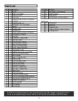
Страница 12: ...G 18 1 FASCIA F LEFT SIDE SHELF 19 1 FASCIA F RIGHT SIDE SHELF 20 1 MAIN CONTROL PANEL 21 2 TEMPERATURE GAUGE UFC MOUNTED 22 1 HOSE VALVE REGULATOR ASSY 23 1 MATCH HOLDER 24 2 BEZEL F CONTROL KNOB 25 2 CONTROL KNOB 26 1 CART UPPER REAR PANEL 27 1 CART LEFT SIDE PANEL 28 1 CART RIGHT SIDE PANEL 29 1 LEFT RAIL F GREASE TRAY 30 1 RIGHT RAIL F GREASE TRAY 31 1 GREASE TRAY 32 1 FRONT DOOR BRACE 33 1 EL...

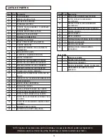
Страница 13: ... TABLERO DE CONTROL PRINCIPAL 21 2 MEDIDOR DE TEMPERATURA INSTALADO EN EL UFC 22 1 UNIDAD DE VÁLVULA MANGUERA REGULADOR 23 1 PORTAFÓSFOROS 24 2 MARCO PERILLA DE CONTROL 25 2 PERILLA DE CONTROL 26 1 PANEL SUPERIOR TRASERO DEL CARRITO 27 1 PANEL LATERAL IZQUIERDO DEL CARRITO 28 1 PANEL LATERAL DERECHO DEL CARRITO 29 1 CARRIL DEL LADO IZQUIERDO BANDEJA PARA LA GRASA 30 1 CARRIL DEL LADO DERECHO BANDE...

Страница 14: ...14 PARTS DIAGRAM VISTA ESQUEMÁTICA DE PIEZAS 7 1 3 2 11 14 12 43 6 4 5 10 9 13 16 18 15 23 20 15 8 17 19 21 24 25 36 37 38 22 31 26 32 35 33 34 29 30 28 39 27 41 42 40 14 ...

Страница 15: ...15 2 ASSEMBLY ARMADO 1 Caster pin 1ST 2ND 3RD 1 4 20x1 2 Screw Qty 6 A A 42 41 41 42 28 27 39 39 Clavija para la rueda Tornillo de 1 4 20 x 1 2 Cant 6 ...

Страница 16: ...16 3 4 1 4 20x1 Screw Qty 4 A Fiber Washer Qty 2 B A A A A A B B 1 8 28 27 26 Tornillo de 1 4 20 x 1 Cant 4 Arandela de fibra Cant 2 ...

Страница 17: ...B 1ST 2ND 3RD 1 4 20x1 Screw Qty 4 A A A A B B 32 34 33 35 33 32 Tornillo de 1 4 20 x 1 Cant 4 Arandela de fibra Cant 2 Tie wrap Cordón de amarre Battery AA Batería AA Note remove the tie wraps Nota retire los cordones de amarre ...

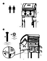
Страница 18: ...18 6 7 10 24x3 8 Screw Qty 4 A 19 15 25 Tornillo de No 10x3 8 Cant 4 A 18 15 A 1ST 2ND ...

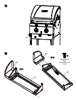
Страница 19: ...19 8 X2 Shoulder Screw Qty 4 1 4 Nut Qty 4 A A A B B 19 15 17 B Tornillo con pivote Cant 4 Tuerca de 1 4 Cant 4 ...

Страница 20: ...rew Qty 2 A B C D 3RD D B 15 17 19 C A Large Flat Washer Qty 2 E Tornillo de 1 4 20 x 1 Cant 2 Tuerca de 1 4 Cant 6 Tornillo autorroscante No 8 de 3 8 Cant 2 Arandela plana grande Cant 2 Tornillo de 1 4 20 x 1 2 Cant 10 B B B C C Tighten the screws Apriete los tornillos 1ST B B 20 20 E 2ND ...

Страница 21: ...21 10 11 A 1ST 8x3 8 self tapping Screw Qty 2 2ND A A 30 29 37 29 30 32 PRESS 1ST 2ND Tornillo autorroscante No 8 de 3 8 Cant 2 OPRIMA ...

Страница 22: ... Infrared emitters must be placed keeping both flat walls overlapped to prevent any flare up IMPORTANTE los emisores infrarrojos deben colocarse de tal forma que se empalmen las dos superficies planas para prevenir llamaradas ...

Страница 23: ...23 14 15 9 10 ...

Страница 24: ...24 16 17 31 ...

Страница 25: ... in operation resulting in the risk of fire 2ND 1ST 40 Tanque de gas propano no viene incluido ADVERTENCIA Una vez que el tanque haya quedado instalado la válvula del tanque debe quedar orientada hacia la parte delantera del carrito Si no se instala correctamente el tanque se puede dañar la manguera de gas durante el suministro lo que puede ocasionar el riesgo de incendio ...

Страница 26: ... for spider nests or rust See Natural Hazard and Cleaning the Burner Assembly pages Turn off control knobs and LP cylinder valve Leave lid open to allow flames to die down After cooling clean food particles and excess grease from inside firebox area grease tray and other surfaces See instructions on control panel and in Use and Care section Make sure valves are positioned inside of burner tubes En...

Страница 27: ... Button is pressed no noise can be heard from spark module SECTION II SECTION III Sparks are present but not at all electrodes and or not at full strength Possible Cause Battery not installed properly Dead battery Button assembly not installed properly Faulty spark module Output lead connections not connected Output lead connections not connected Arcing to grill away from burner s Weak battery Ele...

Страница 28: ...l quemador Cierre las perillas de control y la válvula del cilindro de gas Deje abierta la tapa para permitir que las llamas se extingan Una vez que se haya enfriado limpie las partículas de comida y la acumulación de grasa en la parte interior de la zona de la cámara de combustión la bandeja para la grasa y toda otra superficie Lea las instrucciones en el tablero de control y en la sección titula...

Страница 29: ...ión Resolución de problemas Encendido electrónico Problema encendido SECCIÓN I SECCIÓN II SECCIÓN III Hay chispas pero no en todos los electrodos y o no a plena potencia Causas probables La pila no está instalada adecuadamente Pila gastada Módulo de chispas defectuoso Las conexiones del cable de salida no están bien hechas Las conexiones del cable de salida no están bien hechas El arco de la parri...

Страница 30: ...30 NOTES NOTAS ...

Страница 31: ...31 ...

Страница 32: ......

Отзывы: