background image

45

GB

CN

Gr

Fr

SP

PT

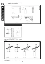
Flue duct terminal

Coaxial

Vertical two-pipe

Horizontal two-pipe

Outer

duct

diameter

100 mm

80 mm
80 mm

Max. length 

of flue duct 


5 m


15 m


30 m

Each 90° bend

reduces the duct

max. length by

1 m

0,5 m
0,5 m

Each 45° bend

reduces the duct

max. length by

0,5 m

0,25 m
0,25 m

Flue

terminal 

diameter

100 mm
133 mm

-

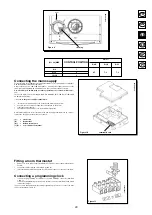
Figure 6

Boiler size

2.24 CF 

2.24 FF 

Installation of flue and air ducts

(2.24 CF)

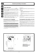
We guarantee ease and flexibility of installation for a gas-fired forced draft boiler thanks 
to the fittings and fixtures supplied (described below).
The boiler is especially designed for connection to an exhaust flue / air ducting, with 
either coaxial, vertical or horizontal terminal. By means of a splitting kit a two-pipe system 
may also be installed.

Exclusively install fittings supplied by the manufacturer.

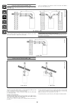
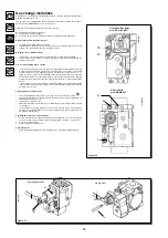
Figure 7

020221_1200

securing clamp

seal

restrictor (*)

Figure 8

...coaxial flue - air duct (concentric)

This type of duct allows to disengage exhaust gases and to draw combustion air both 
outside the building and in case a LAS flue is fitted.
The 90° coaxial bend allows to connect the boiler to a flue-air duct in any direction as it 
can rotate by 360°. It can moreover be used as a supplementary bend and be coupled 
with a coaxial duct or a 45° bend.

(*) The restrictor must be removed in case the flue duct length exceeds  1 m.

If the flue outlet is placed outside, the flue-air ducting must protrude at least 18mm out 
of the wall to allow alluminium weathering tile to be fitted and sealed to avoid water 
leakages.
Ensure  a  minimum  downward  slope  of  1  cm  towards  the  outside  per  each  metre  of 
duct length.

A 90° bend reduces the total duct length by 1 metre.
A 45° bend reduces the total duct length by 0.5 metre.

0609_0705

 /

 CG_1792

0503_0904

 /

 CG_1636

0503_0905

 /

 CG_1638

Содержание initia MASTER 2.24 CF

Страница 1: ... s and User s Instructions Chaudière murale à gaz à haut rendement Notice d emploi destinée à l utilisateur et à l installateur MASTER 2 24 FF MASTER 2 24 CF Caldera mural de gas de alto rendimiento Caldeira mural a gás de alto rendimento Manual de uso destinado al usuario y al instalador Manual para o uso destinado ao utente e ao instalador ...

Страница 2: ...vices 51 Electronic board calibration 52 Positioning of the ignition and flame sensing electrode 52 Check of combustion parameters 52 Output pump head performances 52 Boiler schematic 53 54 Illustrated wiring diagram 55 56 Technical data 57 Dear Customer We are sure your new boiler will comply with all your requirements Purchasing one of the CHAPPEE products satisfies your expectations good functi...

Страница 3: ...ensed technician Ensure the following operations are carried out a compliance of boiler parameters with electricity water gas supply systems settin gs b compliance of installation with the laws and regulations in force c appropriate connection to the power supply and grounding of the appliance Failure to observe the above will render the guarantee null and void Prior to commissioning remove the pr...

Страница 4: ...stays off but the voltage remains present in the electric circuits of the apparatus Prolonged standstill of the system Frost protection central heating system We recommend you avoid draining the whole system as water replacements engen der purposeless and harmful limestone deposits inside the boiler and on the heating elements In case the boiler is not operated during wintertime and is therefore e...

Страница 5: ...ning it see section Turning off the boiler Flashing LED anomaly signals Description Solution Call the authorized Technical Assistance Service Momentarily move the selector 1 to position Call the authorized Technical Assi stance Service Call the authorized Technical Assi stance Service Turn selector switch 1 to the position for a moment See system filling chapter on page Momentarily move the select...

Страница 6: ...orough cleaning has been carried out in that residual combustion products may come off during operation of the boiler and obstruct the flue duct To ensure correct operation of the appliance and avoid invalidating the guarantee observe the following precautions 1 Hot water circuit if the water hardness is greater than 20 F 1 F 10 mg calcium carbonate per litre of water install a polyphosphate or co...

Страница 7: ...tings supplied by the manufacturer Figure 7 020221_1200 securing clamp seal restrictor Figure 8 coaxial flue air duct concentric This type of duct allows to disengage exhaust gases and to draw combustion air both outside the building and in case a LAS flue is fitted The 90 coaxial bend allows to connect the boiler to a flue air duct in any direction as it can rotate by 360 It can moreover be used ...

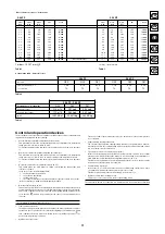
Страница 8: ... This type of installation can be carried out both on a flat or pitched roof by fitting a terminal an appropriate weathering tile and sleeve supplementary fittings supplied on demand L max 4 m L max 4 m L max 3 m L max 2 m For detailed instructions concerning the installation of fittings refer to the technical data accompanying the fittings 0503_0906 CG_1639 0503_0907 CG_1640 0503_0908 CG_1641 ...

Страница 9: ...r duct adaptor For the air duct adaptor fit the screws and seals previously removed from the cap The restrictor must be removed in case you install separated flue and air duct termi nals The 90 bend allows to connect the boiler to flue air ducting regardless of direction as it can be rotated by 360 It can moreover be used as a supplementary bend to be coupled with the duct or with a 45 bend 020130...

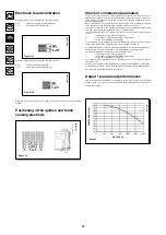
Страница 10: ...lue and intake ducts for the combustion air Turn this control clockwise to increase excess combustion air and anticlockwise to decrease it The maximum length of the suction duct must be 10 metres If the flue duct exceeds 6 m the condensate collection kit supplied as an accessory must be fitted close to the boiler To improve optimisation a combustion product analyser can be used to measure the CO2 ...

Страница 11: ...ws securing the control board to the boiler rotate the control board unscrew the lid and gain access to the wiring Figure 10 A 2A fast blowing fuse is in cor po rated in the power supply terminal block to check or replace the fuse pull out the black fuse carrier L Live brown N Neutral blue Ground yellow green 1 2 room thermostat terminal Figure 10 020130_0900 terminal board Figure 11 9402250715 Fi...

Страница 12: ...nt of the manometer to a T fitting in order to join the boiler adjusting outlet the gas valve adjusting outlet Pc and the manometer The same measurement can be carried out by connecting the manometer to the pressure test point Pb after removing the sealed chamber front panel If you measure the pressure of burners by different means you may obtain an altered result in that the low pressure created ...

Страница 13: ...witch allows the main burner to switch on provided the exhaust flue duct efficiency is perfect In the event of one of the following faults the flue terminal is obstructed the venturi is obstructed the fan is blocked the connection between the venturi and the air pressure switch is not active the boiler will stay on stand by and the light 4 will flash Overheat thermostat 2 24 CF Thanks to a sensor ...

Страница 14: ...ustion products in case of coaxial pipelines The following parameters can be measured at the connection point on the flue gas circuit temperature of the combustion products oxygen O2 or carbon dioxide CO2 concentration carbon monoxide CO concentration The combustion air temperature must be measured at the connection point on the air intake circuit inserting the measurement probe to a depth of abou...

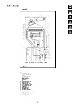
Страница 15: ...nition electrode 6 flue water exchanger 7 DHW NTC sensor 8 flue adaptor 9 fan 10 negative pressure point 11 air pressure switch 12 positive pressure point 13 central heating NTC sensor 14 flame sensing electrode 15 main burner 16 expansion vessel 17 automatic air vent 18 pump and air separator 19 manometer 20 safety valve 21 automatic by pass 22 DHW flow priority microswitch 23 boiler filling tap ...

Страница 16: ...s valve 4 gas train with injectors 5 ignition electrode 6 flue water exchanger 7 DHW NTC sensor 8 flue gas hood 9 flue gas thermostat 10 central heating NTC sensor 11 flame sensing electrode 12 main burner 13 expansion vessel 14 automatic air vent 15 pump and air separator 16 manometer 17 safety valve 18 boiler filling tap 19 DHW flow priority microswitch 20 automatic by pass 21 overheat thermosta...

Страница 17: ...eter P3 Central heating potentiometer P4 S W OFF selector JP1 MET GPL gas change jumper JP2 Heating in standby time 3 10 jumper flame sensing ELECTRODE safety ther mostat dhw ntc sen sor dhw flow priority micro switch hydraulic differential pressure microswitch pump air pressure switch ignition ELECTRODE central heating ntc sensor fan roome thermo stat 230v feeding power grid fusE feeding terminal...

Страница 18: ... Central heating potentiometer P4 S W OFF selector JP1 MET GPL gas change jumper JP2 Heating in standby time 3 10 jumper 0309_2302 flame sensing ELECTRODE safety thermo stat dhw ntc sensor dhw flow priority microswitch hydraulic differential pressure microswitch pump flue gas thermostat ignition ELECTRODE central heating ntc sensor roome thermo stat 230v feeding power grid fusE feeding terminal bl...

Страница 19: ...ific output l min 11 11 Concentric flue duct diameter mm 60 Concentric air duct diameter mm 100 2 pipe flue duct diameter mm 80 2 pipe air duct diameter mm 80 Discharge pipe diameter mm 120 Max flue mass flow rate kg s 0 020 0 021 Min flue mass flow rate kg s 0 017 0 018 Max flue temperature C 146 120 Min flue temperature C 106 86 Type of gas used G20 G20 G30 G31G30 G31 Natural gas feeding pressur...

Страница 20: ...εσθ ύν στην ηλεκτρ νική πλακέτα 70 Τ π θέτηση ηλεκτρ δί υ ανά λε ης και ανί νευσης λ γας 70 Έλεγ ς παραµέτρων καύσης 71 Επιδ σεις παρ ής ε δ υ µαν µετρικ ύ ύψ υς στην πλάκα 71 Σ ηµατικ διάγραµµα λέ ητα 72 73 Εικ ν γρα ηµέν διάγραµµα συνδεσµ λ γίας 74 75 Τε νικά αρακτηριστικά 76 Αγαπητέ Πελάτη είµαστε έ αι ι τι νέ ς σας λέ ητας θα ικαν π ιήσει λες τις απαιτήσεις σας Η αγ ρά εν ς πρ ϊ ντ ς της CHAPP...

Страница 21: ...ικ π ί ς θα ελέγ ει α τη συµµ ρ ωση των παραµέτρων τ υ λέ ητα ηλεκτρικ ρεύµα νερ αέρι µε τις ρυθµίσεις των συστηµάτων τρ δ σίας Τη συµµ ρ ωση της εγκατάστασης µε την ισ ύ υσα ν µ θεσία τµήµα τ υ π ί υ αναδηµ σιεύεται στ τε νικ εγ ειρίδι για τ ν εγκαταστάτη γ την κατάλληλη ηλεκτρική σύνδεση και γείωση της συσκευής ι διευθύνσεις των ε υσι δ τηµένων Κέντρων Σέρ ις αναγρά νται στ σ ετικ έντυπ Η µη τήρ...

Страница 22: ...εις 2 7 δεί ν υν τη θερµ κρασία π υ επιτυγ άνεται απ τ σύστηµα θέρµανσης ή εστ ύ νερ ύ ανάλ γα µε τ εάν υπάρ ει αίτηση θερµ τητας για θέρµανση ή για εστ νερ Σε περίπτωση ανωµαλίας τύπ ς της ανωµαλίας αυτής εµ ανί εται µέσω ένδει ης π υ ΑΝΑΒ ΣΒΗΝΕΙ Σε τι α ρά την ένδει η 4 στ ν πίνακα ειριστηρίων τ υ λέ ητα µπ ρεί να εµ ανιστεί τ σύµ λ για τα µ ντέλα µε στεγαν θάλαµ µη ανικ ύ ελκυσµ ύ ή τ σύµ λ για...

Страница 23: ...ή εκτ ς λειτ υργίας λ κε άλαι σ ήσιµ τ υ λέ ητα στη σελ 58 Ένδει η ανωµαλίας Led π υ ανα σ ήν υν Περιγρα ή Απ κατάσταση Τ π θετήστε στιγµιαία τ διακ πτη επιλ γής 1 στη θέση ιακ πή αερί υ Καλέστε τ ε υσι δ τηµέν Σέρ ις Τ π θετήστε στιγµιαία τ διακ πτη επιλ γής 1 στη θέση Καλέστε τ ε υσι δ τηµέν Σέρ ις Παρ υσία αλάτων στ κύκλωµα εστ ύ νερ ύ ανι νευτής θέρµανσης έ ει υπ στεί λά η ļ Ï ÛÙÂ ÙÔ ÂÍÔ ÛÈÔ Ô...

Страница 24: ...ισ ύσει η εγγύηση είναι απαραίτητ να λη θ ύν τα ακ λ υθα µέτρα 1 Κύκλωµα εστ ύ νερ ύ εάν η σκληρ τητα τ υ νερ ύ είναι µεγαλύτερη απ 20 F 1 F 10 mg ανθρακικ ύ ασ εστί υ ανά λίτρ νερ ύ απαιτείται η εγκατάσταση δ σ µετρητή π λυ ωσ ρικών αλάτων ή άλλων ανάλ γων συστηµάτων σύµ ωνα µε την ισ ύ υσα ν µ θεσία 2 Κύκλωµα θέρµανσης 2 1 νέα εγκατάσταση Πριν την εγκατάσταση τ υ λέ ητα τ σύστηµα πρέπει να καθαρ...

Страница 25: ...στική µ ύ α ιά ραγµα Eικ να 8 µ α νικ ς µ κεντρικ ς αγωγ ς απαγωγής αναρρ ησης αγωγ ς αυτ ύ τ υ τύπ υ επιτρέπει την απαγωγή των καυσαερίων και την αναρρ ηση τ υ αέρα καύσης τ σ απ τ ε ωτερικ τ υ κτιρί υ σ και απ καπν δ υς τύπ υ LAS Η µ α νική γωνία 90 επιτρέπει τη σύνδεση τ υ λέ ητα στ υς αγωγ ύς απαγωγής αναρρ ησης πρ ς π ιαδήπ τε κατεύθυνση άρη στη δυνατ τητα περιστρ ής κατά 360 Επιπλέ ν µπ ρεί ...

Страница 26: ... αγωγ ύς Η εγκατάσταση µπ ρεί να γίνει είτε µε κεκλιµένη είτε µε επίπεδη στέγη ρησιµ π ιώντας τ ε άρτηµα καµινάδας και τ ειδικ κεραµίδι µε τσιµ ύ α π υ διατίθεται κατ πιν παραγγελίας L max 4 m L max 4 m L max 3 m L max 2 m Για λεπτ µερέστερες δηγίες σ ετικά µε την τ π θέτηση των ε αρτηµάτων συµ υλευθείτε τις τε νικές δηγίες π υ συν δεύ υν τα ε αρτήµατα 0503_0906 CG_1639 0503_0907 CG_1640 0503_0908...

Страница 27: ...υ ρακ ρ αναρρ ησης αέρα π υ θα ρησιµ π ιηθ ύν είναι αυτές π υ α αιρέθηκαν πρ ηγ υµένως απ τ καπάκι Τ διά ραγµα π υ υπάρ ει στ λέ ητα πρέπει να α αιρεθεί σε περίπτωση εγκατάστασης µε αυτ ύς τ υς αγωγ ύς Η γωνία 90 επιτρέπει τη σύνδεση τ υ λέ ητα στ υς αγωγ ύς απαγωγής και αναρρ ησης πρ ς π ιαδήπ τε κατεύθυνση άρη στη δυνατ τητα περιστρ ής κατά 360 Επιπλέ ν µπ ρεί να ρησιµ π ιηθεί ως ε εδρική γωνία ...

Страница 28: ...αγωγής και αναρρ ησης τ υ αέρα καύσης αγωγ ς αναρρ ησης πρέπει να έ ει µέγιστ µήκ ς 10 µέτρα Σε περίπτωση π υ τ µήκ ς τ υ αγωγ ύ απαγωγής υπερ αίνει τα 6 µέτρα είναι αναγκαία η εγκατάσταση κ ντά στ λέ ητα τ υ κιτ νερ παγίδας τ π ί διατίθεται ως α εσ υάρ Γυρίστε τ ειριστήρι δε ι στρ α για να αυ ήσετε τ πλε νασµα αέρα καύσης και αντίστρ α για να τ µειώσετε Για απ τελεσµατικ τερη ελτίωση µπ ρείτε να ...

Страница 29: ...ταν συνδεθεί σωστά σε απ τελεσµατική εγκατάσταση γείωσης σύµ ωνα µε τ υς ισ ύ ντες καν νισµ ύς ασ αλείας για τις εγκαταστάσεις λέ ητας πρέπει να συνδεθεί µε µ ν ασικ δίκτυ τρ δ σίας 220 230 V γείωση µέσω τ υ διατιθέµεν υ τριπ λικ ύ καλωδί υ τηρώντας την π λικ τητα Γραµµή υδέτερ Η σύνδεση πρέπει να γίνεται µέσω διπ λικ ύ διακ πτη µε άν ιγµα επα ών τ υλά ιστ ν 3 mm Σε περίπτωση αντικατάστασης τ υ ηλ...

Страница 30: ...στικής αλ ίδας και τ µαν µετρ Η ίδια µέτρηση µπ ρεί να γίνει συνδέ ντας τ µαν µετρ στ σηµεί δ κιµής Pb α ύ έ ετε α αιρέσει τ µπρ στιν κάλυµµα τ υ στεγαν ύ θαλάµ υ Αν µετράτε την πίεση καυστήρων µε άλλη µέθ δ µπ ρεί να γάλετε άλλ απ τέλεσµα επειδή η υπ πίεση π υ δηµι υργείται στ θάλαµ απ τ ν ανεµιστήρα δεν λαµ άνεται υπ ψιν Γ1 Ρύθµιση για την ν µαστική ισ ύ Αν ί τε την άνα αερί υ και περιστρέψτε τ ...

Страница 31: ...24 FF 2 24 CF τύπ ς αερί υ G20 G30 G31 G20 G30 G31 διάµετρ ς µπεκ 1 28 0 74 0 74 1 18 0 74 0 74 αρ µπεκ 13 13 13 13 13 13 Πίνακας 2 2 24 FF 2 24 CF Κατανάλωση στ υς 15 C 1013 mbar G20 G30 G31 ν µαστική ισ ύς 2 78 m3 h 2 07 kg h 2 04 kg h Μειωµένη ισ ύς 1 12 m3 h 0 84 kg h 0 82 kg h p c i 34 02 MJ m3 45 6 MJ kg 46 3 MJ kg Πίνακας 3 mbar mbar mbar kW kcal h G20 G30 G31 2 3 4 8 6 3 9 3 8 000 2 6 5 4 ...

Страница 32: ... δι ανί νευσης π υ ρίσκεται στη δε ιά πλευρά τ υ καυστήρα εγγυάται την ασ αλή λειτ υργία σε περίπτωση διακ πής της παρ ής αερί υ ή ατελ ύς εσωτερικής ανά λε ης τ υ κεντρικ ύ καυστήρα Στις συνθήκες αυτές λέ ητας τίθεται σε κατάσταση εµπλ κής Για την απ κατάσταση των µαλών συνθηκών λειτ υργίας πρέπει να γυρίσετε πρ ς στιγµή τ ειριστήρι 1 στη θέση Υδραυλικ ς πιε στάτης Τ σύστηµα αυτ επιτρέπει τ άναµµ...

Страница 33: ...νι νευτή µέτρησης κατά περίπ υ 3 cm Για τα µ ντέλα λέ ητα υσικ ύ ελκυσµ ύ είναι αναγκαία η διάν ι η πής στ ν αγωγ απαγωγής καυσαερίων σε απ σταση απ τ λέ ητα 2 ρές µεγαλύτερη απ την εσωτερική διάµετρ τ υ αγωγ ύ Μέσω της πής αυτής µπ ρ ύν να µετρηθ ύν ι ακ λ υθες παράµετρ ι θερµ κρασία πρ ϊ ντων της καύσης συγκέντρωση υγ ν υ O2 ή εναλλακτικά δι ειδί υ τ υ άνθρακα CO2 συγκέντρωση µ ν ειδί υ τ υ άνθρ...

Страница 34: ... ης 6 εναλλάκτης νερ ύ καυσαερίων 7 ανι νευτής NTC εστ ύ νερ ύ 8 καπν δ ς 9 ανεµιστήρας 10 παρ ή αρνητικής πίεσης 11 πιε στάτης αέρα 12 παρ ή θετικής πίεσης 13 ανι νευτής NTC θέρµανσης 14 ηλεκτρ δι ανί νευσης λ γας 15 καυστήρας 16 δ εί διαστ λής 17 αυτ µατη αλ ίδα ε αέρωσης 18 αντλία µε νερ παγίδα 19 µαν µετρ 20 αλ ίδα ασ αλείας 21 αυτ µατ by pass 22 αισθητήρας πρ τεραι τητας εστ ύ νερ ύ 23 στρ ιγ...

Страница 35: ...αερί υ 4 γραµµή αερί υ µε µπεκ 5 ηλεκτρ δι ανά λε ης 6 εναλλάκτης νερ ύ καυσαερίων 7 ανι νευτής NTC εστ ύ νερ ύ 8 καπν δ ς 9 θερµ στάτης καυσαερίων 10 ανι νευτής NTC θέρµανσης 11 ηλεκτρ δι ανί νευσης λ γας 12 καυστήρας 13 δ εί διαστ λής 14 αυτ µατη αλ ίδα ε αέρωσης 15 αντλία µε νερ παγίδα 16 µαν µετρ 17 αλ ίδα ασ αλείας 18 στρ ιγγα πλήρωσης λέ ητα 19 αισθητήρας πρ τεραι τητας εστ ύ νερ ύ 20 αυτ µα...

Страница 36: ...ύ P3 Π τενσι µετρ θέρµανσης P4 ιακ πτης επιλ γής E I OFF JP1 Jumper αλλαγής αερί υ ΜΕΘ LPG JP2 Jumper ρ ν υ αναµ νή σε λειτ υργία θέρµανσης 3 10 ΗΛΕΚΤΡ Ι ΑΝΙ ΝΕΥΣΗΣ ΘΕΡΜ ΣΤΑΤΗΣ ΑΣΦΑΛΕΙΑΣ ΑΝΙ ΝΕΥΤΗΣ NTC ΕΣΤ Υ ΝΕΡ Υ ΑΙΣΘΗΤΗΡΑΣ ΠΡ ΤΕΡΑΙ ΤΗΤΑΣ ΕΣΤ Υ ΝΕΡ Υ Υ ΡΑΥΛΙΚ Σ ΠΙΕ ΣΤΑΤΗΣ ΑΝΤΛΙΑ ΠΙΕ ΣΤΑΤΗΣ ΑΕΡΑ ΗΛΕΚΤΡ Ι ΑΝΑΦΛΕ ΗΣ ΑΝΙ ΝΕΥΤΗΣ NTC ΘΕΡΜ ΑΝΕΜΙΣΤΗΡΑΣ ΘΕΡΜ ΣΤΑΤΗΣ ΩΜΑΤΙ Υ 230V ΙΚΤΥ ΗΛΕΚΤΡΙΚΗΣ ΤΡ Φ ΣΙΑΣ Α...

Страница 37: ...Π τενσι µετρ θέρµανσης P4 ιακ πτης επιλ γής E I OFF JP1 Jumper αλλαγής αερί υ ΜΕΘ LPG JP2 Jumper ρ ν υ αναµ νή σε λειτ υργία θέρµανσης 3 10 0309_2302 ΗΛΕΚΤΡ Ι ΑΝΙ ΝΕΥΣΗΣ ΘΕΡΜ ΣΤΑΤΗΣ ΑΣΦΑΛΕΙΑΣ ΑΝΙ ΝΕΥΤΗΣ NTC ΕΣΤ Υ ΝΕΡ Υ ΑΙΣΘΗΤΗΡΑΣ ΠΡ ΤΕΡΑΙ ΤΗΤΑΣ ΕΣΤ Υ ΝΕΡ Υ Υ ΡΑΥΛΙΚ Σ ΠΙΕ ΣΤΑΤΗΣ ΑΝΤΛΙΑ ΘΕΡΜ ΣΤΑΤΗΣ ΚΑΥΣΑΕΡΙΩΝ ΗΛΕΚΤΡ Ι ΑΝΑΦΛΕ ΗΣ ΑΝΙ ΝΕΥΤΗΣ NTC ΘΕΡΜ ΘΕΡΜ ΣΤΑΤΗΣ ΩΜΑΤΙ Υ ΙΚΤΥ ΗΛΕΚΤΡΙΚΗΣ ΤΡ Φ ΣΙΑΣ ΑΣΦΑΛΕ...

Страница 38: ...35 C l min 9 8 9 8 Ειδική παρ ή l min 11 11 ιάµετρ ς µ κεντρικ ύ αγωγ ύ απαγωγής mm 60 ιάµετρ ς µ κεντρικ ύ αγωγ ύ αναρρ ησης mm 100 ιάµετρ ς ωριστ ύ αγωγ ύ απαγωγής mm 80 ιάµετρ ς ωριστ ύ αγωγ ύ αναρρ ησης mm 80 ιάµετρ ς αγωγ ύ απαγωγής mm 120 Μέγιστη παρ ή καυσαερίων max kg s 0 020 0 021 Ελά ιστη παρ ή καυσαερίων min kg s 0 017 0 018 Μέγ θερµ κρασία καυσαερίων C 146 120 Ελά θερµ κρασία καυσαερίω...

Страница 39: ...0609_1503 ...

Страница 40: ...0 335 1 EN 50165 EN 60529 EN 61000 EN 55014 BAXI S p A also declares that this appliance is tested in heating and sanitary mode working with gas with a pressure of 12 bar on the hydraulic sanitary circuit with a pressure of 4 5 bar on the hydraulic heating circuit with an electrical safety control in compliance to the European Standards EN 60 335 1 0011210200 ...

Страница 41: ...as a contract with a third party Ediz 2 11 06 CHAPPEE soucieuse de l amélioration constante de ses produits se réserve le droit de modifier les données mentionnées dans cette notice à tout moment et sans préavis Cette notice est un support d information qui ne peut être considéré comme contrat vis à vis de tiers CHAPPEE na constante acção de melhoramento dos produtos reserva se a possibilidade de ...

Страница 42: ...INITIA MASTER SPARE PARTS CATALOGUE September 2006 ...

Страница 43: ......

Страница 44: ...eginning of production of a component taken from the serial number of the boiler e g B005 year 2000 B identifies the decade 2000 2009 0 identifies the year 5 th week If the box is empty the component is in use from the beginning of production of the boiler To serial number Date year and week identifying the end of production of a component taken from the serial number of the boiler e g B012 year 2...

Страница 45: ......

Страница 46: ......

Страница 47: ... GASKET GUARNIZIONE TAPPO ASPIRAZIONE 5407400 l l l 15 JOINT ASSEMBLY D 100 L 20 with screws GIUNTO D 100 L 20 VERN 5664050 l l l 18 FLUE PLASTIC VENTURI VENTURI INCLINATO 5409580 l l l 21 GASKET 6 1X12X1 5 WRC GUARNIZIONE 6 1X11 5X1 5 WRC 5402050 l l l 22 FAN 1 SPEED VENTILATORE 1 VELOCITÀ 5663810 l l l 23 FAN PRESSURE SWITCH PRESSOSTATO FUMI 5663820 l l l 24 COMPENSATION PIPE L 130 TUBO PRESA CO...

Страница 48: ...13 F U D 1 28 612960 l l l 44 L P G INJECTORS KIT TRASFORMAZIONE MET GPL 5666390 l l l 44 NATURAL GAS INJECTORS KIT TRASFORMAZIONE GPL MET 5666400 l l l 45 GAS RAMP GASKET GUARNIZIONE RAMPA 5407940 l l l 46 GAS RAMP CONNECTING FLANGE RACCORDO FLANGIATO PIANO 5211030 l l l 47 GASKET GAS RAMP SEALED CHAMBER GUARNIZ RACCORDO RAMPA CS 5404760 l l l 49 HOSE ADAPTER CAP TAPPO PER PRESA DI PRESSIONE 5409...

Страница 49: ...IMIT THERMOSTAT 105 C TERMOST LIM 105 C C FAST PIEG 9950760 l l l 137 GAS PIPE TUBO GAS 5663690 l l 1 137 GAS PIPE TUBO GAS 5669650 l 2 140 GAS VALVE SIT 845063 SIGMA VALVOLA GAS SIT 845063 SIGMA 5658830 l l l 140 GAS VALVE HONEYWELL VK4105M 5033 V GAS HON VK4105M 5033 C CAPP 5665220 l 5 147 CONNECTION TRAVERSE TRAVERSA PORTARAC VERNICIATA 5113780 l l l 147 CONNECTION TRAVERSE TRAVERSA PORTARAC VE...

Страница 50: ...TRON 5663770 l l l 314 FLAME SENSING ELECTRODE CABLE CAVO CANDELA RIVELAZIONE 8418870 l l l 340 SAFETY CH PRESSURE SWITCH PRESSOSTATO RISCALDAMENTO 5663750 l l l 371 DRAINING PIPE TUBO CARICAMENTO 5663790 l l l B323 371 DRAINING PIPE TUBO CARICAMENTO 5667990 l l l B323 NO 423 GAS VALVE CONNECTION RACCORDO VALVOLA GAS 5210410 l l l 6 472 DHW OUTLET PIPE ASS TUBO U S 5663760 l l l 511 O RING 17 86X2...

Страница 51: ...45063 SIGMA gas valve 5658830 1 Da usare solo con la valvola a gas SIT 845063 SIGMA 5658830 2 To use only with Honeywell VK4105M 5033 gas valve 5665220 2 Da usare solo con la valvola a gas Honeywell VK4105M 5033 5665220 5 To use with gas pipes 5669650 end 5670420 5 Abbinato ai tubi gas 5669650 e 5670420 6 To use only with Honeywell VK4105M 5033 gas valve 5665220 6 Abbinato alla valvola a gas Honey...

Отзывы: