background image

Champion Compressors Ltd. 

Manual No. 975203 Rev H 


66


23.0 

LEAD / LAG CONTROL BOX DOOR ASSEMBLY 


Содержание ci 110

Страница 1: ...Parts and Operator s Manual Ci 40 Ci 110 Read this manual prior to installation and operation of this machine Manual No 975203 Rev H Effective July 2002 Model _____________ Serial Number _____________ ...

Страница 2: ......

Страница 3: ...E START CHECKS 10 7 1 Location 10 7 2 Connection To Air System 10 7 3 Electrical Connection 11 7 3 1 Ci 40 75 Stop start control 11 7 3 2 Ci 75 110 Star delta CSU 12 7 3 3 Motor Rotation Direction 12 7 4 Mechanical Checks 13 7 4 1 Airend Check 13 7 4 2 Oil Level Check 13 7 4 3 Vee Belt Check 13 7 4 4 System Isolating Gate Valve Check 14 8 0 OPERATION 15 8 1 Start Up Procedure 15 8 2 Function Of Co...

Страница 4: ...5 10 0 MAINTENANCE 26 10 1 General 26 10 2 Daily Operation 26 10 3 Maintenance Schedule 27 10 3 1 Initial Service 250 hours 27 10 3 2 Every 1 500 Hours 27 10 3 3 Every 3 000 Hours Or Yearly 27 11 0 GENERAL ASSEMBLY COMPONENTS Ci 40 55 30 12 0 GENERAL ASSEMBLY COMPONENTS Ci 75 34 13 0 GENERAL ASSEMBLY COMPONENTS Ci 110 40 14 0 INTEGRATED SCREW COMPONENTS Ci 40 55 44 15 0 INTEGRATED SCREW COMPONENTS...

Страница 5: ...ors Ltd Manual No 975203 Rev H 24 0 LEAD LAG CONTROL BOX ASSEMBLY 68 25 0 DUPLEX ASSEMBLIES 70 26 0 TROUBLESHOOTING 72 27 0 GENERAL ARRANGEMENT DRAWINGS 73 29 0 CHAMPION NETWORK 91 APPENDIX A DN METRIC NOMINAL SIZES 94 ...

Страница 6: ......

Страница 7: ...arest Champion Branch or Champion Distributor from whom the compressor was purchased see 29 0 Champion Network If for any reason parts cannot be obtained in this manner please contact Champion Compressors Head Office directly When ordering parts please be careful to check with your part number selection for either assembly or kit If you have any questions please contact your nearest Champion Branc...

Страница 8: ...ntroller Ci 40 55 278905 1 Inlet Controller Ci 75 110 278830 1 Airend Seal Kit Ci 40 110 278763 1 Sight Glass Kit Ci 40 110 278780 1 O ring Kit Ci 40 110 278874 1 Tensiometer 270965 1 2 4 Upgrade Kits Cyclonic Air Filter Kit Ci 40 55 159022 Cyclonic Air Filter Kit Ci 75 110 159023 No Neutral Hour Meter Ci 40 55 159021 Clean Air Pack CRD006 Ci 40 159036 Clean Air Pack CRD009 Ci 55 159037 Clean Air ...

Страница 9: ...ine control and adjustment Easy access to service components Compact modular design which allows for flexible installation and complete package models with air receiver and refrigerant dryer all mounted on the one unit Integrated thermovalve optimised for ambient conditions This operator s manual is written to assist the end user in gaining maximum use from their compressor unit Please familiarise...

Страница 10: ...wn the compressor isolate and bleed the compressor air receiver before attempting to remove the oil filler cap Vent all internal pressure before opening any line fitting valve drain plug connection or other component If you are unsure how to do this contact your nearest Champion Service Agent Do not vary pressure switch setting from those listed in Section 8 3 without prior approval from Champion ...

Страница 11: ...making adjustments or repairs to exposed live parts of the system maintain dry footing stand on insulating surfaces and do not contact any other portion of the compressor Make adjustments with one hand only so as to minimise the possibility of creating a current path through the heart Do not leave the compressor unattended with open electrical enclosures If necessary to do so disconnect and lock o...

Страница 12: ...wish to vary the operating pressure of your machine As standard each compressor is mounted on an air receiver The Ci 40 55 is mounted on one 150L air receiver and the Ci 75 110 are mounted on twin tank 220L air receivers Optionally each model can be accompanied by a clean air package consisting of a refrigerated dryer and microcoalescing filter Each model is also available in a version mounted on ...

Страница 13: ...assemblies Unlike other rotary screw air compressors the integrated rotary screw airend performs the task of multiple system components This has the advantage of reducing the number of connections between components and also reducing system complexity The integrated screw rotors draw air through the air filter and intake controller Oil is injected into the compression space to provide cooling seal...

Страница 14: ...itch then de energises the solenoid valve closing the intake valve and allowing the integrated screw to reduce sump pressure On the stop start models standard on Ci 40 55 75 the compressor will come to a stop The load unload models standard Ci 110 will continue to unload producing no air for a set time governed by the setting of the run on timer after which the compressor will enter standby mode r...

Страница 15: ...2 9 15 7 17 3 9 9 22 8 14 3 o load 415 50 A 8 1 8 9 11 1 12 2 14 7 16 2 9 3 21 2 13 4 Setting 440 60 A 8 8 9 7 11 8 12 9 15 4 16 0 9 7 22 3 14 1 Australia Cable Size mm 1 0 1 5 1 5 2 5 Fuse Size MOTOR START A 25 32 35 35 Oils Factory Fill Mineral SMARTLUBE CH46 SMARTLUBE CH46 SMARTLUBE CH46 SMARTLUBE CH46 High Ambient Mineral SHELL CORENA S68 SHELL CORENA S68 SHELL CORENA S68 SHELL CORENA S68 Synt...

Страница 16: ...arge duct must not recirculate to the air intake Do not install in an area where exhaust fumes from other equipment can be drawn into the intake or other toxic noxious or corrosive fumes chemicals or substances Where more than one compressor is installed in one location not only must proper care be taken with regard to access to each individual machine but special attention should be taken to ensu...

Страница 17: ...3 1 Ci 40 75 Stop start control All the mains supply leads connect to the compressor within the cover of the combination pressure switch and starter There is connection for 3 phases earth and neutral Note The neutral connection is made on the shunt relay contact block located inside pressure switch cover at terminal C1 marked on the relay Please refer to circuit diagram supplied with your machine ...

Страница 18: ... direction This can be checked by toggling the Off Auto switch located on the pressure switch starter Stop Start or the compressor lid Star Delta CSU Note that if your machine is fitted with an auto restart facility there may be a delay of up to 30 seconds after toggling the Off Auto switch The motor and airend rotate in the direction indicated by the arrow marked D on the airend and motor fan cow...

Страница 19: ...m Check that all belts are seated in their grooves The belt tension is maintained by sliding the motor via adjusting jacking bolts located at the feet of the motor Correct belt tension is achieved with the use of a Tensiometer Champion Part No 270965 Refer to Figure 3 Set the large o ring so that the o ring bottom is at the 7mm mark Ensure that the small o ring is set at the zero mark Hold the top...

Страница 20: ...ially tensioned to 1 3 times the maximum running tension settings outlined above Belt tension needs to be adjusted five minutes after these belts are fitted and the compressor is run then again ten minutes later This will ensure that the belts have completed their initial stretch After this first fifteen minutes of operation the belts should be correctly tensioned to the table above Fig 3 Belt Ten...

Страница 21: ...the Auto position indicated on the pressure switch Stop Start models Warning Do not restart the unit within 30 seconds of shutdown This allows the separator vessel to fully vent and prevents starting against load Should the machine show any excessive vibration shut down and contact the Champion Customer Support Division immediately To shut the compressor down turn the Off Auto switch to the Off po...

Страница 22: ...ut it may be adjusted with specific installation requirements Please refer to Champion Compressors prior to any adjustments being made as an incorrect setting may result in damage to the compressor The compressor may start at any time whilst the compressor is in Auto mode Please note that if your machine is fitted with Auto Restart option there may be a starting delay of up to 30 seconds after pow...

Страница 23: ...ansport it will be necessary to adjust them on site This is accomplished as follows refer Figure 4 1 Remove the protective cover from the pressure switch assembly 2 a To increase pressure turn range screw clockwise b To reduce pressure turn range screw anticlockwise 3 a To increase differential turn differential screw clockwise b To reduce differential turn differential screw anticlockwise For saf...

Страница 24: ...ce the unit has cooled down The Star delta CSU models motor overload located in the enclosure once tripped must be manually reset After any fault the Off Auto switch must be toggled to start the compressor In all instances of compressor stopping due to a protection trip urgent action must be taken to rectify the fault prior to the compressor being restarted 8 5 Thermo Bypass Valve All the Dominato...

Страница 25: ...functions should be alternated between the two units by regularly reversing the selector switch on a periodic daily or weekly basis Duty Standby operation may be selected as an alternative to Lead Lag Power is supplied to one compressor only the duty compressor In the event that the duty compressor must be stopped eg routine service the standby compressor may be called upon so that there is no int...

Страница 26: ...te switch to the terminals contained within the control box Two Hour Meters to record hours run for each compressor are mounted inside the control box No mains neutral wire is required for compressors fitted with this option unless the Clean Air Pack is included Refer Section 9 5 9 1 1 Central Control Box Operation The control box offers a number of configurations in which to operate the two compr...

Страница 27: ...switch determining which compressor will supply the base air supply for the demand As stated above the Lead and Lag functions should be alternated between the two units by regularly reversing the selector switches on a periodic daily or weekly basis Note The control box does not have the facility to set both units to Lead or both to Lag This configuration is neither useful or advisable Local or Re...

Страница 28: ...ds The lead and lag functions should be alternated between the two units by regularly reversing the selector switch on a periodic daily or weekly basis 9 2 1 Lead Lag Control Box Operation The lead lag control box offers lead lag only in which to operate the two compressor units Refer Fig 6 Fig 6 Control Panel Lead Lag Control Box The Lead A Lead B selector switch determines which compressor will ...

Страница 29: ...load Pressure kPa Lag Load Pressure kPa Lag Unload Pressure kPa 780 80 700 780 650 730 1000 80 920 1000 870 950 If the settings have drifted during transport it will be necessary to adjust them on site This is accomplished as follows refer Figure 7 1 a To increase pressure turn range screw anticlockwise b To reduce pressure turn range screw clockwise 2 a To increase differential turn differential ...

Страница 30: ...ter Cyclopac For operation in dirty environments a heavy duty Cyclonic air filter is offered as an externally mounted option Refer Section 18 9 7 No Neutral Hour meter Ci 40 55 75 Where no neutral facility exists at the installation location the no neutral option may be fitted allowing connection with three phase power leads and an earth lead Also included is an hour meter to record hours run not ...

Страница 31: ...r correct compressor operation 9 10 Sump Heater and Thermal Fan A sump heater is available to enable the machine to stay warm when not in operation and to prevent condensation from mixing with oil This option is advisable in the cases of a low load cycle low ambient temperature and a humid environment The sump heater option requires a dedicated 240V connection The thermal fan switch option is desi...

Страница 32: ...ed down time Champion Compressors offers a variety of Maintenance Management solutions which provide regular maintenance to ensure long life and trouble free service from your compressor Contact your Champion Compressors representative to arrange this service 10 2 Daily Operation Prior to starting drain any water from oil sump through drain valve until oil begins to flow Oil floats on water Check ...

Страница 33: ...pected and unblocked Access is gained by removing the purge line sight glass Drain all air receivers Except with long life lubricant synthetic analyse sample and change if required 10 3 3 Every 3 000 Hours Or Yearly Perform all checks listed for Every 1 500 hours as well as the following Replace separator element Check condition of inlet controller service if necessary Check condition of Minimum P...

Страница 34: ...Champion Compressors Ltd Manual No 975203 Rev H 28 THIS PAGE HAS BEEN LEFT BLANK ...

Страница 35: ...Champion Compressors Ltd Manual No 975203 Rev H 29 A R As Required N S S Not Sold Separately ...

Страница 36: ...Champion Compressors Ltd Manual No 975203 Rev H 30 11 0 GENERAL ASSEMBLY COMPONENTS Ci 40 55 ...

Страница 37: ...rend Oil Discharge to Cooler 1 10a N S S Elbow 9 16 JIC x 1 2 BSPP Part of Item 10 1 10b N S S Nipple 9 16 JIC x 3 8 BSPT Part of Item 10 1 11 681495 Hose Assy 1 2 Airend Air Discharge to Receiver 1 11a N S S Nipple 3 4 JIC x 1 2 BSPT Part of Item 11 2 12 601079 Taptite M6 x 16 A R 13 601037 Bolt Hex Hd M10 x 30 12 14 601091 Washer M10 Mudguard 8 15 601086 Washer M10 Spring 4 16 621010 Plug Hex Ga...

Страница 38: ...Champion Compressors Ltd Manual No 975203 Rev H 32 11 0 GENERAL ASSEMBLY COMPONENTS Ci 40 55 Continued ...

Страница 39: ...ar 1 35 411036 Taperlock Bush Airend 1610 25 Ci 40 55 1 35a N S S Grub Screw Part of Item 33 2 Motor Pulleys 36 401304 Pulley 2 SPZ x 95 1610 T L Ci 40 7 10 13 bar 1 401312 Pulley 2 SPZ x 106 1610 T L Ci 55 13 bar 1 401284 Pulley 2 SPZ x 118 1610 T L Ci 55 7 10 bar 1 37 411172 Taperlock Bush Motor 1610 28 Ci 40 1 411164 Taperlock Bush Motor 1610 38 Ci 55 1 37a N S S Grub Screw Part of Item 32 2 38...

Страница 40: ...Champion Compressors Ltd Manual No 975203 Rev H 34 12 0 GENERAL ASSEMBLY COMPONENTS Ci 75 ...

Страница 41: ...Air Aftercooler to Receiver 1 10a N S S Nipple 1 BSPT x 1 BSPT 1 10b N S S Elbow 1 1 16 JIC x 3 4 BSPT 1 11 681696 Hose Assembly 1 2 Oil Discharge to Cooler Inlet 1 11a N S S Elbow 3 4 JIC x 1 2 BSPP 1 11b N S S Nipple 9 16 JIC x 1 2 BSPP 1 12 872539 Panel Belt Guard Cover 1 15 601037 Bolt Hex Hd M10 x 30 8 16 872538 Panel Belt Guard 1 17 872442 Angle Door 2 18 872391 Panel Rear 1 19 872313 Panel ...

Страница 42: ...Champion Compressors Ltd Manual No 975203 Rev H 36 12 0 GENERAL ASSEMBLY COMPONENTS Ci 75 Continued ...

Страница 43: ...1067 Plug Hex Blk 3 4 BSPT 1 51 621064 Plug Hex Blk 1 8 BSPT 2 52 781002 Gauge Air Pressure 63 Dia 1600 kPa Rear Entry 1 53 601053 Bolt ZP M12 x 75 2 54 601282 Bolt ZP M12 x 100 2 58 541268 Valve Safety 1 4 BSP 1335 kPa 6mm orifice 1 59 601395 Grommet 16mm 1 60 621571 Adaptor Swivel 1 4 BSPF x 1 4 BSPM 1 61 711078 Reducer PVC 25 20 2 62 711079 Cable Gland PVC M20 2 63 601035 Bolt Hex Hd M10 x 20 4...

Страница 44: ...Champion Compressors Ltd Manual No 975203 Rev H 38 12 0 GENERAL ASSEMBLY COMPONENTS Ci 75 Continued ...

Страница 45: ...ued Item Part No Description Qty 76 861018 Seal Strip 15mm wide A R 77 861089 Handle Pocket Ci Series 1 78 861099 Gas Strut 200N 210 Stroke 1 79 872440 Panel Electrical Door 1 80 9800747 5 Sound Foam Roof Panel Front 2 81 9800747 3 Sound Foam Roof Panel Top Large 2 82 9800747 9 Sound Foam Roof Panel Top Small 1 ...

Страница 46: ...Champion Compressors Ltd Manual No 975203 Rev H 40 13 0 GENERAL ASSEMBLY COMPONENTS Ci 110 ...

Страница 47: ...9800747 3 Sound Foam Roof Panel Top Large 1 18 9800747 9 Sound Foam Roof Panel Top Small 1 19 9800747 6 Sound Foam Right End Panels 2 20 9800747 7 Sound Foam Left End Panels 2 21 9800747 4 Sound Foam Service Door 1 22 9800747 1 Sound Foam Rear Panel 1 23 9800747 2 Sound Foam Front Panel Cut Out 1 23a 9800747 8 Sound Foam Front Panel Large 1 24 9800747 10 Sound Foam Front Panel Small 1 25 601091 Wa...

Страница 48: ...Champion Compressors Ltd Manual No 975203 Rev H 42 13 0 GENERAL ASSEMBLY COMPONENTS Ci 110 Continued ...

Страница 49: ...harge to Cooler Inlet 1 45a N S S Nipple 9 16 JIC x 1 2 BSPT 1 45b N S S Nipple 9 16 JIC x 1 2 BSPP 1 46 741005 Pressure Switch XMP 1 741013 Pressure Switch XMP 13 bar 1 47 621609 Nipple 1 4 BSPT 2 48 621011 Tee Gal 1 4 BSP 1 49 781002 Gauge Air Pressure 63 Dia 1600 kPa Rear Entry 1 50 621571 Adaptor Swivel 1 4 BSPF x 1 4 BSPM 1 51 601079 Taptite M6 x 16 A R 52 601037 Bolt Hex Hd M10 x 30 8 53 601...

Страница 50: ...Champion Compressors Ltd Manual No 975203 Rev H 44 14 0 INTEGRATED SCREW COMPONENTS Ci 40 55 ...

Страница 51: ... 14 278780 Sight Glass Purge Line Part of Sight Glass Kit 1 15 278775 Minimum Pressure Valve 1 16 N S S Oil Filler Cap 1 17 N S S Element Thermovalve 70º C 1 N S S Element Thermovalve 80º C Export 1 18 N S S O ring 1 19 N S S Cover Thermovalve 1 20 N S S Slide Thermovalve 1 21 N S S Spring 1 22 278877 Element Oil Filter Cartridge 1 23 N S S Oil Filter Base 1 24 N S S O ring 1 25 N S S O ring 1 26 ...

Страница 52: ...Champion Compressors Ltd Manual No 975203 Rev H 46 15 0 INTEGRATED SCREW COMPONENTS Ci 75 110 ...

Страница 53: ...ass Kit 1 15 278775 Minimum Pressure Valve 1 16 N S S Oil Filler Cap 1 17 N S S Element Thermovalve 70º C 1 N S S Element Thermovalve 80º C Export 1 18 N S S O ring 1 19 N S S Cover Thermovalve 1 20 N S S Slide Thermovalve 1 21 N S S Spring 1 22 278877 Element Oil Filter Cartridge 1 23 N S S Oil Filter Base 1 24 N S S O ring 1 25 N S S O ring 1 26 N S S O ring 1 27 N S S Copper Washer 2 28 N S S C...

Страница 54: ...Champion Compressors Ltd Manual No 975203 Rev H 48 16 0 ELECTRICAL STARTER ASSEMBLY Ci75SD 110 ...

Страница 55: ...ontactor Line Delta CL03 A301MR GE 2 12 712044 Overload 10 16 A GE Ci 110 1 712043 Overload 8 12 A GE Ci 75SD 1 13 712205 Interlock Mechanical Electrical bela 1 14 712027 Contactor Star CL02 A301TR GE 1 15 712162 Timer Star Delta 1 16 711075 Fuse Holder 3 17 N S S Cover Fuse Holder Part of Item 17 3 18 711222 Fuse Link 4A 1 19 711221 Fuse Link 2 A 2 20 711075 Fuse Holder Export Option 1 21 N S S C...

Страница 56: ...Champion Compressors Ltd Manual No 975203 Rev H 50 16 0 ELECTRICAL STARTER ASSEMBLY Ci75SD 110 Continued ...

Страница 57: ...inued Item Part No Description Qty 33 712004 Emergency Stop Button 1 33a N S S Locknut Button 1 34 712067 On Off Switch 2 Position 1 34a N S S Locknut Button 1 35 712160 Reset Button Auto Restart Option 1 35a N S S Locknut Button 1 36 781009 Hour Meter 1 36a N S S Hour Meter Bracket 1 37 671139 Gasket Hour Meter 1 ...

Страница 58: ...Champion Compressors Ltd Manual No 975203 Rev H 52 17 0 CLEAN AIR PACK ASSEMBLIES ...

Страница 59: ... CRD009 1 621561 Nipple Hex Red BSPT x 3 8 BSPT CRD006 1 9 601147 Taptite Hex Washer Face M8x36 4 10 601037 Bolt M10 x 30 4 11 601091 Washer M10 Mudguard 4 12 601086 Washer M10 Spring 4 Clean Air Pack Components Ci 75 Ci 110 15 182012 Refrigerated Dryer Champion CRD012 1 182018 Refrigerated Dryer Champion CRD018 1 16 521327 Dryer Mount W A CRD012 2 521328 Dryer Mount W A CRD018 2 17 681700 Hose As...

Страница 60: ...Champion Compressors Ltd Manual No 975203 Rev H 54 17 0 CLEAN AIR PACK ASSEMBLIES Continued ...

Страница 61: ...lement 211554 Micro Filter Champion G3A 211754 G3A Filter Element 211555 Micro Filter Champion G5V 211755 G5V Filter Element 211556 Micro Filter Champion G5ZP 211756 G5ZP Filter Element 211557 Micro Filter Champion G5XP 211757 G5XP Filter Element 211558 Micro Filter Champion G5A 211758 G5A Filter Element 211559 Micro Filter Champion G7V 211759 G7V Filter Element 211560 Micro Filter Champion G7ZP 2...

Страница 62: ...Champion Compressors Ltd Manual No 975203 Rev H 56 18 0 CYCLOPAC AIR INTAKE ASSEMBLIES ...

Страница 63: ...Bolt Hex Hd Zinc PL M8 x 20 4 11 631025 Tube Fitting Str Conn x 1 8 BSPM 1 12 681002 Tube Nylon A R 13 631024 Tube Fitting Elbow x 1 8 BSPM 1 Ci 75 110 14 861077 Seal Strip P Mould Nitrile 1 15 N S S Air Filter Cover 1 16 561200 Clamp Hose Worm Drive 35 to 53 mm 1 17 561354 Clamp Hose Worm Drive 40 to 60 mm 3 18 561454 Reducer Rubber 2 to 1 1 19 681583 Tube Aluminised 2 80 x 80 1 20 681582 Hose Ru...

Страница 64: ...Champion Compressors Ltd Manual No 975203 Rev H 58 19 0 ACOUSTIC HOOD ASSEMBLY ...

Страница 65: ...uard 580 x 125 x 100 1 5 872393 Panel Front 820 x 340 x 95 1 6 872416 Panel Belt Guard Mounting 2 7 872417 Panel Belt Guard Cover 1 8 601079 Taptite Cross Recess Pan Head M6 x 16 19 9 861018 Seal Strip 15 mm wide A R 10 861089 Handle Pocket Ci Series 2 11 9800700 1 Sound Insulation Foam 309 x 820 x 25 1 12 9800700 2 Sound Insulation Foam 309 x 820 x 25 1 13 9800700 3 Sound Insulation Foam 190 x 82...

Страница 66: ...Champion Compressors Ltd Manual No 975203 Rev H 60 20 0 AUTODRAIN ASSEMBLY ...

Страница 67: ... ASSEMBLY 9800992 Rev A Item Part No Description Qty 1 621559 Elbow BSPF Swivel x BSPM 1 2 621676 Nipple Hex 316SS BSP 1 3 621672 Tee 316SS BSP 1 4 631003 Fitting T x BSPTM Str 2 5 681826 Tube Nylon 25m 6 621670 Elbow M F BSP 316SS 1 7 202017 Kit Autodrain To 240V 1 ...

Страница 68: ...Champion Compressors Ltd Manual No 975203 Rev H 62 21 0 CONTROL BOX DOOR ASSEMBLY ...

Страница 69: ... Switch or Lamp Labelled 16 3 712145 Lens Cap Green 3 4 712146 Lens Cap Yellow 2 5 712147 Lens Cap Red 2 6 712148 Globe 24V 7 7 712149 Base Globe 7 8 712004 Push Button Emergency Stop 1 9 712000 Push Button Flush Start 2 10 712001 Push Button Flush Stop 2 11 712091 Switch Selector 3 Position 1 12 712067 Selector Switch 2 Position 3 13 712003 Contact Block N C 6 14 712002 Contact Block N O 4 ...

Страница 70: ...Champion Compressors Ltd Manual No 975203 Rev H 64 22 0 CENTRAL CONTROL BOX ASSEMBLY ...

Страница 71: ...11829 Relay Base 4 Pole 2 10 711062 Relay 240V 2 Pole 6 11 711981 Relay 24V 2 Pole 4 12 711574 Relay 240V 4 Pole 2 13 711048 Terminal Block 51 14 711349 Terminal Block Earth 4 15 711046 Terminal Block End Cover 4 16 741004 Pressure Switch 2 17 591007 Pressure Switch Fitting 2 18 631051 Fitting Tube Elbow 1 4 T x 1 4 BSPM 1 19 681002 Tube Nylon 1 4 A R 20 631026 Fitting Tube Tee 1 4 T x 1 4 BSPM 1 ...

Страница 72: ...Champion Compressors Ltd Manual No 975203 Rev H 66 23 0 LEAD LAG CONTROL BOX DOOR ASSEMBLY ...

Страница 73: ... Stop 1 3 712067 Selector Switch 2 Position 1 4 712127 Selector Switch Illuminated Green 2 Position 2 5 712335 Push Button Flush Reset 1 6 712145 Lens Cap Green 1 7 712147 Lens Cap Red 2 8 712158 Globe 240V 5 9 712157 Base Globe 5 10 712079 Contact Block N C N O 2 11 712002 Contact Block N O 2 12 712003 Contact Block N C 3 13 712114 Contact Block N O N O 1 14 712334 Electrical Enclosure 300 x 400 ...

Страница 74: ...Champion Compressors Ltd Manual No 975203 Rev H 68 24 0 LEAD LAG CONTROL BOX ASSEMBLY ...

Страница 75: ... 711221 Fuse Link 2 Amp 2 5 711222 Fuse Link 4 Amp 1 6 712184 Transformer 415 240V 60VA 1 7 712063 Relay Base 2 Pole 4 8 711062 Relay 2 Pole 4 9 711048 Terminal Block 4mm sq 4 10 711349 Terminal Block Earth 4mm sq 3 11 711047 Terminal End Cover 1 12 741004 Pressure Switch 2 13 591007 Pressure Switch Fitting 2 14 631051 Fitting Tube Elbow T x BSPM 1 15 631026 Fitting Tube Tee T x BSPM 1 16 601138 L...

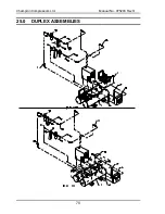
Страница 76: ...Champion Compressors Ltd Manual No 975203 Rev H 70 25 0 DUPLEX ASSEMBLIES ...

Страница 77: ...1 3 872347LH Panel Mounting Bracket Left Hand 1 4 872347RH Panel Mounting Bracket Right Hand 1 5 681567 Hose 3 4 To Be Cut To Size 4m 5a N S S Hose Discharge to Wet Air Receiver 2 5b N S S Hose Wet Air Receiver to Filter 1 5c N S S Hose Filter to Dryer Inlet 1 5d N S S Hose Dryer Outlet to Filter 1 5e N S S Hose Filter to Dry Air Receiver 1 8 631051 Fitting Tube Elbow 1 4 T x 1 4 BSPM 1 9 681002 T...

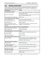
Страница 78: ...n Align Drive System Check Intake Valve Operation Check Solenoid Valve Operation if necessary replace 26 3 Motor starts and compressor does not load CSU S D Only Plant pipework already pressurised Faulty solenoid valve Lower system pressure Replace solenoid valve 26 4 Compressor does not provide enough air Too much air usage Inlet filter blocked Throttle not opening fully Contact Champion Compress...

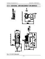
Страница 79: ...Champion Compressors Ltd Manual No 975203 Rev H 73 27 0 GENERAL ARRANGEMENT DRAWINGS Fig 8 Ci 40 55 Standard ...

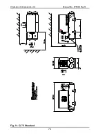
Страница 80: ...Champion Compressors Ltd Manual No 975203 Rev H 74 Fig 9 Ci 75 Standard ...

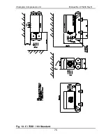
Страница 81: ...Champion Compressors Ltd Manual No 975203 Rev H 75 Fig 10 Ci 75SD 110 Standard ...

Страница 82: ...Champion Compressors Ltd Manual No 975203 Rev H 76 Fig 11 Ci 40 55 Acoustic Hood ...

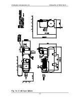
Страница 83: ...Champion Compressors Ltd Manual No 975203 Rev H 77 Fig 12 Ci 40 Dryer Option ...

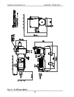
Страница 84: ...Champion Compressors Ltd Manual No 975203 Rev H 78 Fig 13 Ci 55 Dryer Option ...

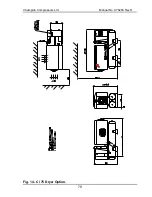
Страница 85: ...Champion Compressors Ltd Manual No 975203 Rev H 79 Fig 14 Ci 75 Dryer Option ...

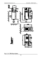
Страница 86: ...Champion Compressors Ltd Manual No 975203 Rev H 80 Fig 15 Ci 75SD Dryer Option ...

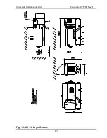
Страница 87: ...Champion Compressors Ltd Manual No 975203 Rev H 81 Fig 16 Ci 110 Dryer Option ...

Страница 88: ...Champion Compressors Ltd Manual No 975203 Rev H 82 Fig 17 Ci 40 55 Base Mount ...

Страница 89: ...Champion Compressors Ltd Manual No 975203 Rev H 83 Fig 18 Ci 40 55 Base Mount with Acoustic Hood ...

Страница 90: ...Champion Compressors Ltd Manual No 975203 Rev H 84 Fig 19 Ci 75 Base Mount ...

Страница 91: ...Champion Compressors Ltd Manual No 975203 Rev H 85 Fig 20 Ci 75SD 110 Base Mount ...

Страница 92: ...Champion Compressors Ltd Manual No 975203 Rev H 86 Fig 21 Ci 75 Cyclopac Option ...

Страница 93: ...Champion Compressors Ltd Manual No 975203 Rev H 87 Fig 22 Ci 75SD 110 Cyclopac Option ...

Страница 94: ...Champion Compressors Ltd Manual No 975203 Rev H 88 Fig 23 Ci 40 110 Duplex Control Box Clean Air Pack shown ...

Страница 95: ...___________________________________________________ ________________________________________________________________________ ________________________________________________________________________ Ancillaries if applicable Ancillary Details __________________________________________ Condition of filters etc 1 2 3 4 5 How does it compare to your expectations 1 2 3 4 5 Other Comments ______________...

Страница 96: ...Champion Compressors Ltd Manual No 975203 Rev H 90 28 0 CUSTOMER FEEDBACK SHEET Please return fax this document to Champion Compressors 613 9703 8077 ...

Страница 97: ...67 7811 Midcoast Compressed Air Services Jungaburra Gum Scrub Road Gum Scrub NSW 2441 Ph 02 6585 8245 Illawarra Compressed Air Services 28 Jardine St Fairy Meadow NSW 2519 Ph 042 832 366 Fax 042 843 229 Airequip Pty Ltd 5 Cox Close Buff Point NSW 2262 Ph 043 902 666 Fax 043 908 796 SOUTH QUEENSLAND Champion Compressors Ltd 14 Parkview Drive Archerfield QLD 4108 Ph 07 3277 7111 Fax 07 3277 7775 Air...

Страница 98: ...td 15 Central Park Drive Paget Mackay QLD 4740 PO Box 928 Mackay QLD 4740 Ph 07 4944 5900 Fax 07 4944 5999 TASMANIA Total Air Supplies 8 Conway St Mowbray TAS 7248 Ph 03 6326 6311 Fax 03 6326 6459 SOUTH AUSTRALIA Champion Compressors Ltd 3 30 Birralee Road Regency Park SA 5010 Ph 08 8244 5677 Fax 08 8244 5688 KPI Industries 153 155 Commercial St East Mt Gambier SA 5290 Ph 08 8723 2232 Fax 08 8723 ...

Страница 99: ...quipment Co Ltd 54 Soi Phanit Anan Sukhumvit 71 Rd Klongton Nua Wattana Bangkok 10110 Thailand Telephone 66 2 712 1866 8 Fax 66 2 713 1869 Email Integratedmedic ClickTA com New Zealand Secair NZ Ltd 287 Church Street Onehunga Auckland NZ Telephone 0064 963 44 211 Fax 0064 963 44 212 Contact Kerry Waugh Indonesia PT Kompresindo Utamajaya Grand Wijaya Centre J L Wijaya II Block A No 12 A B 2nd Floor...

Страница 100: ...imensions The nominal size is designated by DN followed by a number which shall be shown without the addition of the unit of measure Refer to DN equivalents on the table shown below It should be noted that not all piping components are designated by nominal size for example steel tubes are designated and ordered by outside diameter and thickness NOTE The nominal size DN cannot be subject to measur...

Страница 101: ... PAYMENT IN FULL No warranty claim will be considered unless the Claimant has fully complied with the terms of payment as set down in the conditions of sale or in the quotation for supply of the goods concerned b INSTALLATION ENVIRONMENT The warranty is conditional upon the correct and proper installation and application of the product No claim will be allowed where the environment is hostile to t...

Отзывы: