background image

14

200947 - WALk BEhiND BLOWER

ASSEMBLY

ASSEMBLY

Your blower requires some assembly. This unit ships from the 
factory without oil. It must be properly serviced with fuel and oil 
before operation. For questions regarding the assembly of your 
blower, call our help line at 1-877-338-0999. Please have your 
serial number and model number available.

Remove the Blower from the Shipping Carton

1.  Set the shipping carton on a solid, flat surface.

2.  Remove all contents from the carton.

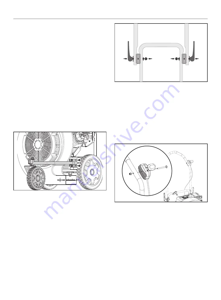
Assemble front Wheel

1.  Align the 4 holes on the front wheel bracket with the 4 holes 

on the blower frame near the rear wheel on the left side of 
the frame (from the user position).

2.  Place a lock washer and flat washer onto each M8 × 20 hex 

bolt. Thread a M8 × 20 hex bolt into each hole and, using a 
13mm wrench, tighten to 15 lbf. ft. - 19 lbf. ft. 
(20.3 - 25.8 Nm)

Assemble Upper handle

1.  Place the upper handle assembly down over the lower handle 

assembly, with the upper handle on the outside, and align the 
teeth of the upper handle adjuster so they seat into the teeth 
on the lower handle adjuster.

2.  From the outside of the handle assembly, insert the threaded 

end of the handle adjust lever through the hole on the upper 
handle assembly and the hole on the lower handle assembly.

3.  Thread a M8 nylon lock nut onto the threaded end of the 

handle adjust lever. Holding the handle adjust lever in place, 
use a 13mm socket or wrench to tighten the lock nut securely 
locking the handle in place. (see operation section for handle 
height adjustment). 

Assemble Throttle Control

1.  Align the throttle control to the outside of the upper left 

handle (from the user position) with the groove against the 
handle and fast speed towards the front.

2.  From the outside of the throttle control, place the M6 × 70 

carriage bolt through the hole on the throttle and through the 
hole on the handle tube.

3.  Thread the M6 nylon lock nut onto the bolt and tighten 

securely.

Содержание 200947

Страница 1: ... could result in serious injury This manual should remain with the product Specifications descriptions and illustrations in this manual are as accurate as known at the time of publication but are subject to change without notice REGISTER YOUR PRODUCT ONLINE at championpowerequipment com WARNING To reduce the risk of injury the user must read and understand the operator s manual before using this p...

Страница 2: ...djust the Handle Height 19 Vertical Air Flow Adjustment 20 Forward Air Flow Attachment 20 Front Wheel Swivel 21 Operation at High Altitude 21 Maintenance 21 Cleaning the Blower 22 Engine Oil Services 22 Cleaning and Adjusting the Spark Plug s 23 Cleaning the Air Filter 23 Cleaning the Spark Arrestor 23 Adjusting the Governor 24 Maintenance Schedule 24 Storage 24 Short Term Engine Storage Up to 30 ...

Страница 3: ...exercise common sense and always err on the side of caution when operating the product to ensure no accident property damage or injury occurs We want you to continue to use and be satisfied with your CPE product for years to come When contacting CPE about parts and or service you will need to supply the complete model and serial numbers of your product Transcribe the information found on your prod...

Страница 4: ...vere laceration can result Keep hands and feet away from rotating parts Tie up long hair and remove jewelry Operate equipment with guards in place DO NOT wear loose fitting clothing dangling drawstrings or items that could become caught DANGER DO NOT allow children or untrained individuals to use this unit WARNING Maintain a firm grip on the handle with both hands while using the blower WARNING Al...

Страница 5: ...place damaged parts WARNING Rotating impeller blades can cause severe injury Stop the engine and ensure impeller blades have stopped rotating before installing changing parts or diverters WARNING Do not point the blower nozzle in the direction of people or pets when in operation WARNING Spark from a removed spark plug wire can result in fire or electrical shock When servicing the engine Disconnect...

Страница 6: ... then an explosion hazard could be created Gasoline expands or contracts with ambient temperatures Never fill the gasoline tank to full capacity as gasoline needs room to expand if temperatures rise When adding or removing gasoline DO NOT light or smoke cigarettes Always turn the blower off and let cool for minimum of two minutes before removing the gasoline cap Afterwards loosen gasoline cap to r...

Страница 7: ...L SF Rev A Size 101 6 x 43 mm Artwork Notes 3mm corner radius 2mm safe margin to be printed on WHITE substrate Revision Changes This artwork belongs to Champion Power Equipment The contents are confidential and privileged and shall not be disclosed to or used by or for outside parties without the explicit consent of Champion Power Equipment Blower Discharge Danger Label C 2018 L OP A ESSENCE SANS ...

Страница 8: ...ion sèche Un pare étincelles peut être nécessaire L utilisateur doit communiquer avec le service d incendie local pour les lois et les règlements relatifs à la prévention des incendies 2303 L SF A ADVERTENCIA Operación de este equipo puede crear chispas que pueden iniciar incendios en vegetación seca Un parachispas puede ser requerido El operador debería contactar las agencias locales de incendios...

Страница 9: ...ult in objects being thrown into your eyes and other possible serious injuries Always wear sound protection ear mufflers or ear plugs to protect your hearing Long term blower noise exposure may damage your hearing Footwear Always wear safety shoes or heavy boots when operating the machine Gloves Always wear nonslip heavy duty protective gloves when operating this product Safety Alert Precautions t...

Страница 10: ...machine may pick up and throw objects which can cause personal injury Check the work area before each use Remove all objects such as rocks where possible broken glass nails wire or string which can be thrown or become entangled in the machine 50 ft 15m Clearance Keep all bystanders children and pets at least 50 15m away when operating the blower Never run the unit without the blower fan cover inst...

Страница 11: ...resting firmly on level ground when checking 2 Add gasoline with a minimum octane rating of 87 and an ethanol content of less than 10 by volume 3 Move the choke lever to CHOKE position 4 Move the throttle lever on the handle at the user position to the FAST position forward 5 Move the fuel valve to OPEN position 6 Pull the starter cord slowly until resistance is felt and then pull rapidly 7 As eng...

Страница 12: ...rence Blower 1 Upper Handle 2 Throttle Speed Control 3 Handle Adjust Lever 4 Lower Handle 5 Engine 6 Rear Wheel 7 Forward Air Flow Attachment 8 Vertical Air Flow Adjustment 9 Front Wheel 10 Front Wheel Swivel Lock 2 1 3 4 6 5 7 8 9 10 Engine 1 Muffler 2 Air Filter 3 Oil Fill Cap Dipstick 4 Recoil Starter 5 Oil Drain Bolt 6 Throttle 7 Choke 8 Fuel Valve 9 Engine OFF Switch 10 Fuel Tank 11 Fuel Gaug...

Страница 13: ...0 Hexagon bolt 4 13mm Wrench Spring washer 4 Flat washer 4 Upper handle 1 M8 Nylon flange lock nut 1 13mm Wrench Throttle control 1 M6x70 carriage bolt 1 10mm Wrench M6 Nylon flange lock nut 1 Forward flow air attachment 1 N A Engine Oil 16 9 fl oz 500 ml 1 N A Engine Oil Funnel 1 N A Parts Not Included Metric Wrench or Socket Set Phillips Screwdriver Pliers ...

Страница 14: ...ce the upper handle assembly down over the lower handle assembly with the upper handle on the outside and align the teeth of the upper handle adjuster so they seat into the teeth on the lower handle adjuster 2 From the outside of the handle assembly insert the threaded end of the handle adjust lever through the hole on the upper handle assembly and the hole on the lower handle assembly 3 Thread a ...

Страница 15: ...ng the dipstick to check oil level DO NOT screw in the dipstick while checking NOTICE Check oil often during the break in period Refer to the Maintenance section for recommended service intervals CAUTION The engine is equipped with a low oil shut off and will stop when the oil level in the crankcase falls below the threshold level NOTICE The first 5 hours of run time is the break in period for the...

Страница 16: ...resh regular unleaded gasoline with a minimum octane rating of 87 and an ethanol content of less than 10 by volume y b c 2 DO NOT mix oil with gasoline 3 Remove the gasoline cap 4 Slowly add gasoline to the tank DO NOT OVERFILL Gasoline can expand after filling A minimum of in 6 4 mm of space left in the tank is required for gasoline expansion although more than in 6 4 mm is recommended Gasoline c...

Страница 17: ... occur on contact Combustible material can catch fire on contact DO NOT touch hot surfaces Avoid contact with hot exhaust gases Allow equipment to cool before touching Maintain at least 3 ft 91 4 cm of clearance on all sides to ensure adequate cooling Maintain at least 5 ft 1 5 m of clearance from combustible materials WARNING Never run the unit without the blower fan cover installed Use of an imp...

Страница 18: ...ng on ambient temperature The colder the temperature the longer the warm up required Stopping the Engine In an emergency turn the engine switch to the OFF position NOTICE If the engine does not stop when the engine switch is moved to the STOP position move the throttle to the slow speed position and slide the choke lever to the cold start closed position Under normal operation 1 Turn the fuel valv...

Страница 19: ...or the unit 4 DO NOT operate the blower if the discharge chute is clogged Remove all debris before operation 5 Always inspect the engine and make sure the oil level and fuel level are correct before operating 6 Always inspect the work area for any distractions or factors that may prevent operator safety or proper operation Adjust the Handle Height The handle height can be adjusted to a comfortable...

Страница 20: ...ment to the discharge chute will direct the air flow to the front of the blower instead of the side 1 Stop the engine see Stopping the Engine section 2 Loosen the attachment knob located on top of the blower discharge chute 3 Orient the attachment so This Side Up for Use is visible and the arrows are oriented toward the discharge chute 4 Slide the attachment over the discharge chute The slot on th...

Страница 21: ...ical Bulletin area of the CPE website The part number and recommended minimum altitude for the application of the high altitude carburetor main jet is listed in the following table In order to select the correct high altitude main jet it is necessary to identify the carburetor model For this purpose a code is stamped on the side of the carburetor Select the correct high altitude jet part number co...

Страница 22: ...d after every five hours of continuous operation Running the engine when it is low on oil will quickly ruin the engine It is recommended that you change the engine oil after every 10 hours of operation and even sooner when operating in extremely dirty or dusty conditions A Check the Engine Oil Level 1 Park the blower on a level area and shut off the engine 2 Clean around the oil dipstick to preven...

Страница 23: ...park required for ignition 4 Make certain the spark plug gap is 0 028 0 031 in 0 7 0 8 mm SPARK PLUG GAP 5 Refer to the spark plug types in Specifications when replacing the plug 6 Firmly re install the plug 7 Attach the spark plug cable to the spark plug Cleaning the Air Filter 1 Using your finger pry the outer tab up slightly and lift the air filter cover above the tab lock position 2 Remove bot...

Страница 24: ...amage your blower and will void your warranty Contact our Technical Support Team at 1 877 338 0999 for all other service and or adjustment needs Maintenance Schedule Follow the service intervals indicated in the following maintenance schedule Service your blower more frequently when operating in adverse conditions Contact our Technical Support Team at 1 877 338 0999 to locate the nearest CPE certi...

Страница 25: ...r any corrosive material Even with an empty fuel tank gasoline vapors could ignite When storing the blower for short or long periods of time always be sure that the engine switch where applicable and the fuel valve where applicable are set in the OFF position NOTICE The engine works well with 10 or less ethanol blend fuels When using blended fuels there are some issues worth noting Ethanol gasolin...

Страница 26: ...ance Change the type of engine oil used based on temperature shown in the Recommended Engine Oil Type table 20 0 20 40 60 Ambient temperature Recommended Engine Oil Type 80 100 120 28 9 F C 17 8 6 7 4 4 15 6 26 7 37 8 48 9 10W 30 5W 30 Full Synthetic 10W 40 5W 30 Oil Capacity fl oz mL 16 9 500 Fuel Specifications Use regular unleaded gasoline with a minimum octane rating of 87 and an ethanol conte...

Страница 27: ...27 200947 Walk Behind Blower Specifications Parts Diagram Figure A 2 3 4 4 5 6 9 10 11 12 13 13 1 8 7 14 15 16 17 18 22 19 20 8 4 21 8 4 23 Figure A 24 ...

Страница 28: ...late 1 10 2540006535 Volute Assembly 1 11 2550011339 Flat Key 4 78 35 1 12 2560004098 Engine R224P B00KY 1 13 2550001556 Nut GB6177 1 M8 6 14 2540006537 Wind direction Adjusting Bracket 1 15 2540006538 Wind direction Plate 1 16 2550011247 Bolt M4 16 2 17 2550011235 Locknut M4 2 18 2560004099 Compression Spring 1 1 19 2540006558 Locking Lever 1 20 2540006539 Outlet Assembly 1 21 2550011240 Hex Bolt...

Страница 29: ...7 Walk Behind Blower Specifications Parts Diagram Figure B 1 2 3 4 5 6 7 8 9 10 11 12 2 20 15 21 22 23 24 21 25 26 27 14 28 29 30 21 24 23 31 32 35 21 33 34 36 19 24 23 21 24 23 18 19 37 38 13 14 16 17 Figure B ...

Страница 30: ...Spring Ø2 1 18 2540006557 Rear Wheel Assembly 12in Yellow 2 19 2550000971 Washer Ø8 3 20 2560004101 Starter Rope Bracket 1 21 2550011239 Gasket Ø8 20 22 2550011238 Nut GB6183 1 M8 2 23 2550011242 Hexagon Bolt M8 20 8 8 18 24 2550000883 Lock Washer Ø8 18 25 2540006562 Handlebar Bracket 2 26 2540006556 Rubber Bushing 4 27 2550001556 Nut GB6177 1 M8 14 28 2540006545 Base Assembly 1 29 2540006546 Forw...

Страница 31: ...ine Parts Diagram 34 35 36 37 38 39 56 57 58 42 68 69 70 59 60 61 62 63 64 65 67 86 87 88 89 90 66 85 91 34 40 41 43 44 45 46 47 48 49 50 51 52 53 54 55 71 72 73 75 76 77 78 79 80 81 82 83 84 92 93 94 94 95 96 96 96 96 97 98 99 100 100 101 74 96 102 ...

Страница 32: ... Z810110 0000 Piston Pin Ø13 Ø45 9 1 29 11310 Z810310 0000 Crankcase Subassembly 1 30 90682 Z300110 0001 Oil Seal Ø25 Ø41 25 6 2 Part Number Description Qty 31 90408 Z010110 0000 Washer Ø10 Ø15 8 1 5 2 32 11007 Z010110 0001 Drain Plug Bolt M10 x1 25 x15 Blue White Zinc 2 33 16400 Z810210 0000 Governor Gear Assembly 1 34 90547 0205 00 Bearing 2 35 90521 Z010110 0000 Square Key 1 36 13300 Z812110 00...

Страница 33: ... 79 16072 Z010110 0001 Governor Support Bolt M6 21 Blue White Zinc 1 80 16063 Z810210 0000 Spring Governor 1 81 16062 Z010110 0001 Governor Rod Blue White Zinc 1 82 16012 Z010310 0000 Throttle Valve Returning Spring 1 83 16520 Z012610 0100 Throttle Control Assembly 1 84 90502 0912 00 Pin 9 12 2 85 16730 Z440810 LK01 Fuel Tank Cap 1 86 16652 Z010810 0001 Fuel Strainer 1 87 37200 Z810210 0001 Fuel G...

Страница 34: ...e filter Carburetor out of adjustment Contact Technical Support Team Stale gasoline Replace with fresh gasoline Dirt or water in fuel tank Contact Technical Support Team Engine cooling system clogged Clean air cooling system Engine Overheats Engine cooling system clogged Clean air cooling system Carburetor out of adjustment Contact Technical Support Team Oil level is low Check oil level Excessive ...

Страница 35: ...lected involved in an accident abused loaded beyond the product s limits or modified Normal maintenance is not covered by this warranty and is not required to be performed at a facility or by a person authorized by CPE Other Exclusions This warranty excludes Cosmetic defects such as paint decals etc Wear items such as starter pulleys starter ropes filter elements belts blower fans impeller blades ...

Страница 36: ...e condition exits CPE will repair your small off road engine SORE and equipment at no cost to you including diagnosis parts and labor MANUFACTURER S WARRANTY COVERAGE This Emissions Control System is warranted for two years If any emissions related part on your small off road engine SORE and equipment is defective the part will be repaired or replaced by CPE OWNER WARRANTY RESPONSIBILITIES As the ...

Страница 37: ...l shall be warranted for the period of time prior to the first scheduled replacement point for that part If the part fails prior to the first scheduled replacement the part shall be repaired or replaced by CPE according to Subsection d below Any such emissions related part repaired or replaced under the ECS Warranty shall be warranted for a time not less than the remainder of the ECS Warranty Peri...

Страница 38: ... Mounting Brackets Carburetor Purge Port Connector TO OBTAIN WARRANTY SERVICE You must take your CPE engine or the product on which it is installed along with your warranty registration card or other proof of original purchase date at your expense to any Champion Power Equipment dealer who is authorized by Champion Power Equipment Inc to sell and service that CPE product during his normal business...

Отзывы: