GB-3
INFRARED SENSOR -
The infrared sensor is a safety-enhancing facility and must be used.
Its installation location depends on the design of the given sliding
gate. Generally speaking, the light barrier is fitted at knee height
approx. 35cm above ground level. Infrared sensors comprise a
transmitter element and a receiver element which have to be located
opposite one another. A screwdriver can be used to open the light
barrier housing (plastic). The infrared sensor is fitted to the wall with
small screws and wall plugs. Usage of a single infrared sensor is a
minimum requirement; we recommend using two infrared sensors
(and other safety features if necessary).
Should a further infrared sensor be active for the OPEN direction of
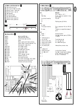
travel, it has to be connected to contact 11 + 12 (stop). This is
necessary if the area behind the gate has to be secured. If contact
strips (accessories) are to be employed as additional safety features,
they also have to be connected to the stop contact.
The transmitter element needs a 2-pole cable, the receiver element a
4-pole one.
Cable cross-sectional area: 0.5mm
2
or more.
Voltage: 12/24 volt AC/DC.
Electrical connections: See control unit instructions.
FLASHING LAMP -
Usage of a flashing lamp is mandatory. It serves a safety-related
purpose in that it warns persons in the vicinity of the gate that the
given gate is moving.
The flashing lamp is fixed in position using screws and wall plugs.
The earthed cable has to be run up to connect with the lamp.
Normally speaking, it is installed at the highest possible point
(on a pillar).
Cable cross-sectional area: 0.75mm
2
, 3-pole
Voltage: 120 volt AC.
Electrical connections: See control unit instructions.
KEY SWITCH -
The key switch can be used to activate the drive as well as open and
close the gate. Cable cross-sectional area: 0.5mm
2
or more.
Electrical connections: See control unit instructions.
INSTALLATION OF AN EXTERNAL ANTENNA
An external antenna is not a mandatory requirement. A short antenna
is located on the control unit's radio adapter. Should the range of the
remote control need to be extended, fit an external antenna
compatible with 433MHz (the ANT4X-1LM model incl. 750 ohm
coaxial cable). It has to be connected up via the radio adapter on the
control unit (see control unit instructions). The best location for an
antenna is high up and as far away from electrical equipment as
possible. The short cable antenna that is supplied as standard and
pre-connected may then no longer be used.
Electrical connections: See control unit instructions.
INITIAL OPERATION
Check gate functionality manually when the drive has been
disengaged. Electrical operation is only possible with the control unit
that is supplied as standard.
Electrical connections: See control unit instructions.
Always ensure that the mechanical and electrical safety requirements
relevant to the given system are complied with.
MAINTENANCE WORK
The drive mechanics are maintenance-free. Check at regular
intervals (monthly) that the gate hardware and the drive are all firmly
in place. Disengage the drive and check gate functionality. Only an
easy-running gate will work well with a drive. A drive is no substitute
for a poorly functioning gate.
A sliding gate can also be secured by implementing on-site
measures (fence, wall, etc.).
See fig. 12.
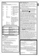
TECHNICAL DATA - CONTROL UNIT
Voltage: 120V~
±10%
60Hz
Max. consumption:
10W
Max. drive supply:
120V~ 60Hz 700VA max
Infrared Sensor supply:
24V~ 0,5A max
Working temperature:
-25ºC – 55ºC
Operating modes:
Automatic / Semi-automatic / Step-by-step / Dead man
Max. running time:
120 sec
Pause period:
8 – 200sec
Dimensions:
109x145mm (without box)
ELECTRICAL INSTALLATION
The CB2-120 control unit is designed to be installed in a special
box under the hood of the sliding gate drive and, as such, can
be ordered as an accessory if not already available. The control
unit can also be accommodated externally (on the wall) in a
watertight box (accessory).
The control unit should be the last item to be connected up, i.e.
mounting the drive, laying the necessary cable and fitting light
barriers (contact strips). If installation is to be performed in a
permanent location, a means of disconnecting the equipment from
the mains supply with a contact clearance of at least 3 mm is needed
(master switch). Humidity and water will destroy the control unit.
Always make sure that water, humidity and condensation cannot
enter the control unit. It is vitally important that all openings and cable
glands are sealed so that they are watertight.
INSTALLATION OF CONTROL BOX
The motor control unit is a microprocessor-controlled electronic
appliance featuring state-of-the-art technology. It is equipped with all
the connecting options and functions needed to guarantee safe
operation. The control box incorporating the motor control unit should
be installed with the cable intakes pointing downwards. It should not
be continuously exposed to direct sunlight. The electronic equipment
enables the pull and push forces to be set with great accuracy. If
installed and set correctly, the gate can be stopped manually.
When in motion, the gate can be stopped at any time by operating
the remote control, the push-button or the key-operated switch.
The gate must be fitted with a robust end stop for the OPEN and
CLOSED positions.
Generally speaking, the following minimum cable cross-
sectional areas must be adhered to:
• 100-230Volt 1,5mm
2
or more
• 0-24Volt 0,5mm
2
or more
Tips:
Bell wire is often problematic in practical use because it loses
too much voltage if long lengths of wire are used.
Segregate the cables in cable trunking, i.e. motor cable and light
barrier cable, especially in the case of key-operated switches and ON
switches (from the house wiring system) to prevent interference
where long lengths of cable are used.
9
9
B
10
10 A
11
11 A
12
TECHNICAL DATA
Voltage IN
Frequency
Power
Current rated
Torque
Capacitor
Therminal Overload
Protection
Motor Speed
Travel Speed
Duty Cycle
Working Temperatur
Range
Protection Class
Degree of Protection
Weight
approx. Gate Length
Max. Gate weight at
max. length (incl.
20% reserve)
SLY500
120Volt
60Hz
360W
1.5A
10Nm
10
140
1400
12
30
-20
O
C - 55
O
C
IP44
I
9
8m
500kg


