


Chapter 2
17
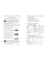
Blinking LED in Suspend Mode:
While in Suspend mode, the LED light on the front panel of your computer will
flash. Suspend mode is entered by pressing the Green Override Power Button on
your ATX case, or by enabling the Power Management and Suspend Mode
options
in BIOS's Power Management menu. (See section
3.5
)
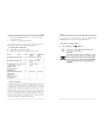
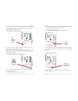
Poly-fuse Over Current Protection:
The poly-fuse protects the system from dangerous voltages that the system might be
exposed to via keyboards or USB connectors. In case of such an exposure, the
poly-fuse will immediately be disconnected from the circuit just like a normal fuse.
After being disconnected for a certain period of time, the poly-fuse will return to its
normal state and the keyboard or USB connector can function properly again.
Unlike conventional fuses, the poly-fuse will not need to be replaced, relieving users
from such inconveniences.
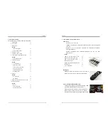
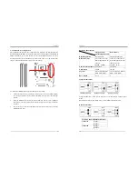
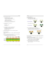
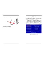
CN1A (Front Panel Connector):
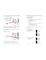
1.
PWR-SW
(Over-ride Power Button Connector):
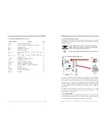
The power button on the ATX chassis can be used as a normal power switch as
well as a device to activate the Advanced Power Management Suspend mode. This
is a power-saving mode used for saving electricity when the computer is not in use
for a long period of time. The Soft-OFF by PWR-BTTN function in BIOS's Power
Management Setup menu must be set to [
Delay 4 Sec.
] to activate this function.
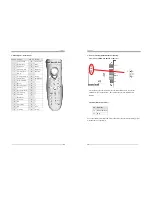
When the Soft-OFF by PWR-BTTN function is enabled, pressing the power button
rapidly will switch the system to Suspend mode. Any occurrence of external
activities such as pressing any keys on the keyboard or moving the mouse will
bring the system back to Full-On. Pushing the button while in Full-On mode for
more than [
4 seconds
] will switch the system completely off. See Over-ride Power
Button Operation diagram.
Chapter 2
18
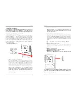
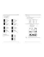
2.
P-LED
(Power LED Connector):
The power indicator LED shows the system's power status. It is important to pay
attention to the correct cables and pin orientation (i.e. Be careful not to reverse the
order of these two connectors.)
3.
G-BTN/G-LED
(Green Button Switch/LED Connector):
Some ATX cases provide a Green button switch, which is used to put the system in
Suspend mode. While in Suspend mode, the power supply to the system is reduced
to a trickle, the CPU clock is stopped, and the CPU core is in its minimum power
state. The system is activated whenever the keyboard or mouse is touched. The
system will resume in various ways as defined by Power Management Setup screen
in BIOS.
For Green LED connector please refer to Section 2.7 CBOX™ 3
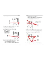
4.
RESET
(System Reset Switch Connector):
This connector should be connected to the reset switch on the front panel of the
system case. The reset switch allows you to restart the system without turning the
power off.
5.
SPEAKER
(Speaker Connector):
This 4-pin connector connects to the case-mounted speakers.
6.
HD-LED
(IDE - Activity LED Connector):
The IDE- activity LED lights up whenever the system reads/writes to the IDE
devices.
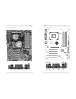
FD1 (Floppy Connector)
The motherboard provides a standard floppy disk drive connector that supports
360K, 720K, 1.2M, 1.44M and 2.88M floppy disk types. A Floppy disk drive of 34
pins is connected using this connector.


