background image

Chapter 2 


15

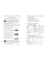
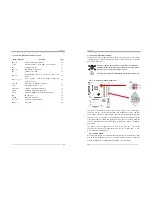
2-4  Connector and Jumper Reference Chart 


Jump Connector 

Function Page 

PW1 / 2 

ATX Power Supply Connector 

16 

CN1A 

Front Panel (Power / Rest / SPK…etc.) Connector 

17 

FD1 Floppy 

Connector 

18 

IDE1 / 2 

IDE Hard-Disk Connector   

19 

JP1 

CMOS Clear Jumper 

19 

JP6 / 6A 

Disable/Enable USB 0/1, 2/3 Device Power ON 
Jumper 

20 

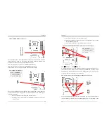
FAN 1 / 2 / 3 / 4 

CPU / System / Case/ North Bridge Cooling Fan 
Connector (12V) 

20 

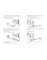
CN5 / 5A 

Wake on LAN / Modem Connector 

21 

CN17 

Blue LED Connector    (5V) 

22 

CN23 / 23A 

CBOX™3 Front USB Connector 

22 

CN24 

CBOX™3 Front Audio Connector 

23 

CN25 

CBOX™3 DigiDoc System Display Connector 

23 

IR1 IR 

Connector 

24 

CN26B IEEE1394 

Connector 

24 

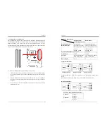
JP3 / 3A 

CPU Front Side Bus setting 

25 

SATA1 / 2 

Serial ATA 

25 


Chapter 2 


16

2-5  Connector and Jumper Settings 

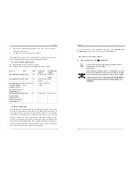
Connectors are used to link the system board with other parts of the system, 
including the power supply, the keyboard, and the various controllers on the front 
panel of the system case. 


The power supply connector is the last connection to be made while 
installing a motherboard. Before connecting the power supply, please 
make sure it is not connected to the power source. 


All cables that provided by CHAINTECH come with a security-proof. 


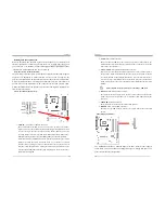
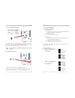
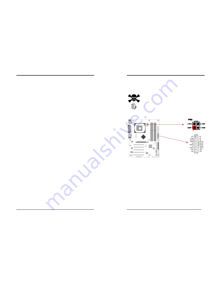
PW 1 / 2 (ATX Power Supply Connector): 


The power cord leading from the system's power supply to the external power 
source must be the very last part connected when assembling a system. The ATX 
power supply provides a single 20-pin connector interface, which incorporates 
st/-5V, +/-12V, optional 3.3V and Soft-power signals. The Soft power signal, 
a 5V trickle supply is continuously supplied when AC power is available. When the 
system is in Soft-Off mode, this trickle supply maintains the system in its minimum 
power state. 
The ATX 12V power supply has a new +12V (4-pin) and +5V / 3.3V (6-pin) 
auxiliary power connector to enable the delivery of more +12 VDC and + 5/ 3.3V 
VDC current to the motherboard. 

Power-On By Modem: 

While in Soft-Off state, if an external modem ring-up signal is detected, the system 
will be activated and therefore can be remotely accessed. You may enable this 
function in BIOS's Power Management Setup menu. (See section

 3. 5

Содержание 9CJS

Страница 1: ... device that complies with 47 CFR Parts 2 and 15 of the FCC Rules Operation is subject to the following two conditions 1 This device may not cause harmful interference 2 This device must accept any interference received including interference that may cause undesired operation This declaration is given to the manufacturer CHAINTECH EXCEL COMPUTER INC 4427 Enterprise St Fremont CA 94538 U S A http ...

Страница 2: ...ice and does not represent a commitment on the part of the vendor No warranty or representation either expressed or implied is made with respect to the quality accuracy or fitness for any particular purpose of this document The manufacturer reserves the right to make changes to the content of this document and or the products associated with it at any time without obligation to notify any person o...

Страница 3: ... Driver Setup 59 4 4 Gigabit Lan Driver 61 4 5 USB 2 0 Driver 63 4 6 WinCinema Pro 63 Appendix 75 A 1 Windows 2000 XP CD ROM Installation 75 A 2 Intel Application Accelerator RAID 76 A 3 Digidoc 80 Port POST Error Code List 83 How To Contact CHAINTECH 89 ...

Страница 4: ...TA devices for the highest data transfer rates 1 5 Gbps burst with RAID 0 solution On board VIA VT6306 IEEE1394 Host Controller Serial bus data rates of 100 200 and 400 Mbps IEEE P1394a compliant and IEEE Std 1394 1995 Programmable ATA ATAPI interface supporting PIO modes 0 4 DMA modes 0 2 and Ultra DMA modes 0 4 Chapter 1 2 Embedded USB 2 0 Host Controller Three EHCI USB 2 0 Controllers support t...

Страница 5: ...es CBOX 3 Fits in any 5 1 4 drive bay DigiDoc displays CPU s temperature and 80 port Post Code during POST at boot up Integrates 6 in 1 Card Reader with USB 2 0 IEEE1394 Headphone Microphone and more Infrared accompanies with Chaintech Handigator sets you free from annoying wires Include USB 1 1 2 0 compliant Ext ports x 2 Earphone 3 5mm phone jack x 1 MIC in 3 5mm phone jack x 1 IEEE 1394 Ext por...

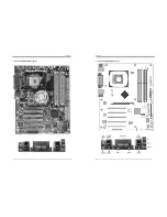
Страница 6: ...Chapter 1 5 1 4 9CJS Motherboard Diagram Chapter 1 6 1 5 9CJS Motherboard Layout ...

Страница 7: ...at sink and fan for proper Heat dispatch Installing a standard Intel specified heat sink with cooling fan is necessary for proper heat dissipation from your CPU Failing to install these items may result in overheating and possible burnout of your CPU In order to boot up with a newly installed CPU AC Power must be switched off before installation Chapter 2 8 2 2 Setting your CPU s Parameters Hyper ...

Страница 8: ...ers through an easy to use BIOS setup procedure Now it is no longer necessary to change the various jumper settings as on conventional motherboard After installing all your hardware into your PC system you can manually configure your CPU clock ratio and CPU clock according to your processor s specifications After turning on your system s power enable the CMOS Setup Utility by pressing delete key w...

Страница 9: ...ntil the golden finger on the memory module is deeply inserted into the socket 3 The plastic clip on each side of the DIMM slot will automatically close to hold the DDR Modules in place Chapter 2 12 Memory Channel Modes Single Channel Virtual Single Channel Dual Channel DIMM Population No restrictions Matching DIMM pairs Rank Row Size Size of one side of the DIMM populated in the channel 64MB 512M...

Страница 10: ...atching as bus width technology and or external banks are different Mixing these DIMMs will put platform into single channel mode Chapter 2 14 Maximizing Performance Optimal configurations for highest performance Matched DDR400 Double sided DIMMs Dual Channel Mode Symmetrical DIMM population Matched DDR400 Dual Channel Mode When not using DDR400 highest performing configuration Symmetrical DIMM po...

Страница 11: ...he last connection to be made while installing a motherboard Before connecting the power supply please make sure it is not connected to the power source All cables that provided by CHAINTECH come with a security proof PW 1 2 ATX Power Supply Connector The power cord leading from the system s power supply to the external power source must be the very last part connected when assembling a system The...

Страница 12: ...ccurrence of external activities such as pressing any keys on the keyboard or moving the mouse will bring the system back to Full On Pushing the button while in Full On mode for more than 4 seconds will switch the system completely off See Over ride Power Button Operation diagram Chapter 2 18 2 P LED Power LED Connector The power indicator LED shows the system s power status It is important to pay...

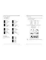
Страница 13: ...set it back to the default position Pin Definition 1 2 Normal default 2 3 Clear CMOS Data Chapter 2 20 3 Connect the system s power and then start the system 4 Enter BIOS s CMOS Setup Utility and choose Load Setup Defaults Type Y and then press Enter to continue 5 Set the system configuration in the Standard CMOS Setup menu JP6 JP6A Enable Disable USB 0 1 2 3 Device Power ON Jumper JP6 USB 0 1 JP6...

Страница 14: ...erface Card that provides WOL function to the motherboard CN5A WOM Wake on Modem Connector Enable the Wake Up On Modem selection in BIOS s Power Management Menu to activate this function This header is used to connect an add in modem card which Chapter 2 22 provides WOM function to the motherboard CN17 Blue LED Connector This feature works exactly the same as the power indicator LED of which both ...

Страница 15: ...n CN25 CBOX 3 DigiDoc System Display Connector CBOX 3 features CHAINTECH s exclusive DigiDoc the most advanced system diagnostic monitoring display 80 PORT diagnostic display during POST at system boot up Chapter 2 24 CPU temperature monitoring your system stays cool always DigiDoc is the doctor for your system Refer to Appendix Digidoc 80 Port POST Error Code List for its details IR 1 IR Connecto...

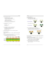
Страница 16: ...for details JP3 JP3A Definition 1 2 1 2 Default OPEN 2 3 133 MHz 2 3 OPEN 200 MHZ Chapter 2 26 2 6 Serial ATA and Parallel ATA SATA PATA configurations 1 Compatible mode Older OSs don t support switch to native mode DOS Win2K Win98 ME should set SATA and PATA to Compatible Mode Maximum 4 ATA devices Combine mode and Non Combine mode 2 Enhanced mode New OS that support switch to native mode WinXP W...

Страница 17: ...f system chassis and securely tighten the side screws 2 Connect Motherboard to CBOX 3 Function Motherboard CBOX 3 USB 4 5 CN23 CN1 USB 6 7 CN23A CN2 Front Audio CN24 CN3 IEEE 1394 CN26B CN4 80 Port Display CN25 CN6 Remove CN24 Jumper Caps on motherboard 5 6 9 10 before installation USB Cable 10 pin x 2 Front Audio Cable 10 pin x 1 IEEE 1394 Cable 8 pin x 1 80 Port Display 10 pin x 1 All cables tha...

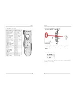
Страница 18: ...t button 31 5 13 Previous Track 32 6 14 Play Pause Multimedia 33 1 15 Next Track 34 2 16 N A 35 3 17 Stop playing 36 0 18 N A 37 dot 19 Volume Up 38 Esc Key Chapter 2 30 2 9 CMC Chaintech Multimedia Card Setup CN2 CN2A CD ROM Audio in Connector Use the audio cable enclosed with your CD ROM disk drive to connect the CD ROM to your motherboard This will enable your CD ROM s audio function JP1 JP2 Ba...

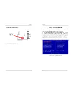
Страница 19: ... power is turned off To enter the Phoenix Award BIOS setup program press Delete when you Power on or reboot the computer system The primary screen as shown in Figure 3 1 is a list of the menus and functions available in the setup program Select the desired item by using arrow keys and press enter to make the changes Operating commands are located at the bottom of this and all other BIOS screens Wh...

Страница 20: ...elect the type of video adapter present in your system You can ignore this setting if you are using a VGA monitor VGA BIOS will automatically configure this setting Halt On When the system is powered on BIOS performs a series of diagnostic tests called Chapter 3 34 POST Power On Self Test This function stops the computer if BIOS detects a hardware error You can tell BIOS to halt on all errors no e...

Страница 21: ...Normal Keyboard Interface 1 Typematic Rate Setting When enabled you can set the following two typematic control items When disabled the keyboard controller determines keystrokes arbitrarily in your system Chapter 3 36 2 Typematic Rate Chars Sec The typematic rate sets the rate at which characters on the screen repeat when a key is pressed and held down 3 Typematic Delay Msec The typematic delay se...

Страница 22: ... However please make sure your components are able to tolerate such abnormal setting while CPU clock speed is overclocked Any attempt to operate beyond product specifications is not recommended We do not guarantee the damages or risks caused by inadequate operation or beyond product specifications System BIOS cacheable Enabling this function allows caching of the system BIOS ROM at F0000h FFFFFh w...

Страница 23: ...r access The onboard IDE drive interfaces supports Prefetching for faster drive accesses Set it to Disabled if this is a primary or secondary function 3 On Chip Primary Secondary PCI IDE You can set this to disable the On Chip IDE controller if you are going to add a higher performance IDE board 4 IDE Primary Secondary Master Slave PIO The four IDE PIO programmed Input Output fields let you set a ...

Страница 24: ...dio card If there is no on board PCI Audio card select Disabled in this field Super IO Device This section provides information on setting the Super I O devices By choosing the Integrated Peripherals option from the CMOS Setup Utility menu Figure 3 5 the screen below is displayed This sample screen contains the manufacturer s default values for the motherboard Chapter 3 42 Press Enter to enter the...

Страница 25: ...nk This function serves as both a screen saver and a power saver 3 DPMS Select this option if your video card supports the Display Power Management Signaling DPMS standard i e you have a monitor that supports Green features Use software supplied by your video subsystem to set video power management options Video off in Suspend This setting determines when the monitor enters power saving mode if it...

Страница 26: ...ystem Chapter 3 46 3 6 PNP PCI Configurations This section provides IRQ and DMA setting information By choosing the PNP PCI Configuration option from the CMOS Setup Utility menu Figure 3 1 the screen below is displayed This screen contains the manufacturer s default values for the motherboard Figure 3 6 PNP PCI Configurations Reset Configuration Data Select Enabled to reset Extended System Configu...

Страница 27: ...ge Control By choosing the Frequency Voltage Control option from the CMOS Setup Utility menu Figure 3 1 the screen below is displayed This sample screen contains the manufacturer s default values for the motherboard Figure 3 8 Frequency Voltage Control CPU Clock Ratio This feature allows users to manually configure your CPU clock ratio according to your processor s specifications Auto Detect PCI C...

Страница 28: ... Figure 3 1 When the Security Option function is set to Setup a password is required to enter BIOS and change BIOS settings When the Security Option function is set to System a password is required to enter both BIOS and computer s operating system For example Windows 98 found on the boot drive The third and fourth variables are user password and supervisor password selected in BIOS Figure 3 1 The...

Страница 29: ...r CD ROM driver or double click the CD drive icon in My computer to enter the setup screen 4 1 Intel IDE Bus Mastering Drivers Setup 1 Select Intel IDE Bus Mastering Drivers 2 Click Next to start software installation Chapter 4 52 3 Click Yes to accept the license agreement 4 Select Next to continue ...

Страница 30: ...allation 4 2 SATA Driver Please refer to Section 2 6 Serial ATA and Parallel ATA and Section 3 4 Integrated Peripherals OnChip IDE Device On Chip Serial ATA for details on Serial ATA 1 Select SATA Driver Chapter 4 54 2 Click Next to continue the setup process 3 After reading the license agreement please click Yes to continue ...

Страница 31: ...ick on Next to proceed 5 Please select one folder from existing list of folders and click on Next to proceed Chapter 4 56 6 Click Finish to complete the setup process Please refer to Appendix for overview on Intel Application Accelerator RAID 4 3 Audio Driver 1 Select Audio driver ...

Страница 32: ...ontinue the installation Chapter 4 58 4 Select 7 1 speakers and click Next to continue This option is only available when users install Windows XP SP 1 or its later versions The option 5 1 speakers is available when Windows 2000 or its previous versions ie Win 2000 Win NT Win Me and Win 9x are installed 5 Click Continue Anyway to proceed ...

Страница 33: ...s to restart computer now or No to restart later and then click on Finish to complete the installation 4 3 Intel LAN Driver Setup 1 Select LAN Driver Chapter 4 60 2 Select Next to continue 3 Click Finish to complete the setup process ...

Страница 34: ...Chapter 4 61 4 4 Gigabit Lan Driver 1 Select Gigabit LAN Driver 2 Click Wired LAN Adapters Chapter 4 62 3 Click Install Base Driver 4 Click OK to continue 5 Click Exit to complete the setup process ...

Страница 35: ...lect from CD ROM intel usb2 win2k_XP ich5usb2_win2k for Win 2000 XP or CD ROM intel usb2 win98 me for 98se ME and then install the system files The host controller should be installed correctly when Device Manager is updated after the install 4 6 WinCinema Pro 1 Select WinCinema Pro Chapter 4 64 2 Select Install InterVideo WinCinema 3 Enter personal information on boxes below to register the produ...

Страница 36: ...P and Clear All to deselect them Click Next to proceed 4 6 1 WinDVD Setup 1 Please click Next to begin the setup process Chapter 4 66 2 After reading the license agreement please click Yes to continue 3 Please select a folder where the program will be installed and click on Next to proceed ...

Страница 37: ... click on Next to proceed 5 Please select the default player by checking the specific boxes and click on Next to proceed Chapter 4 68 6 Please check the box to install the help file and click on Next to proceed 4 6 2 WinRip 2 1 Setup 1 Please click Next to begin the setup process ...

Страница 38: ... Yes to continue 3 Please select a folder where the program will be installed and click on Next to proceed Chapter 4 70 4 Please select one folder name from existing list of folders and click on Next to proceed 5 Click on Start to begin WinRip Configuration Wizard ...

Страница 39: ... Choose Select All to select all file extension types for WinRip and click on Next to continue 7 Click on Next to continue Chapter 4 72 8 Select Yes to continue 9 Click on Finish to complete the configuration process ...

Страница 40: ...k on Finish to complete the setup 11 Please select Yes for restarting computer now or No for restart later then click on Finish to complete installation Chapter 4 74 12 Select Yes to exit now or No to go back to Main Menu ...

Страница 41: ...d by the drivers are not available during Windows 2000 XP setup 3 Choose S to specify an additional device when the screen displays Setup could not determine the type of one or more mass storage devices Note If this screen is not displayed as the first user input and then pressing the F6 key was not seen by the setup program Reboot the system and try again 4 Insert the appropriate Serial ATA drive...

Страница 42: ...nageable blocks These blocks are striped across the different drives of the RAID 0 array By doing this two or more hard drives are combined and the read write performance especially for sequential access can be improved However no redundancy information is stored in a RAID 0 array which means that if one hard drive fails all data is lost This lack of redundancy is also stated in the number 0 which...

Страница 43: ...m The refresh function can be activated by pressing the F5 function key or by clicking on the View menu and then selecting Refresh F5 Other brands and names may be claimed as the property of others Component Overview Displaying Controller and Device Information When opened the Devices window in the Device Information property page contains Appendix 80 entries for the Intel Ultra ATA controller and...

Страница 44: ...ember Disks Lists the disks contained in the RAID volume Component Overview Create View and Delete RAID Volumes Navigation Note You can right mouse click on a device for actions Right click on RAID Volumes to create a new RAID volume After a RAID volume has been created right click on a volume to modify or delete Create a Volume Two methods are provided to create a RAID volume 1 Create Manually Yo...

Страница 45: ... time clock power status and then check for override Appendix 84 14 Program chipset default values into chipset Chipset default values are MODBINable by OEM customers 16 Initial Early_Init_Onboard_Generator switch 18 Detect CPU information including brand SMI type Cyrix or Intel and CPU level 586 or 686 1B Initial interrupts vector table If no special specified all H W interrupts are directed to S...

Страница 46: ...s according to items described in Setup Auto configuration table 6D 1 Assign resources to all ISA PnP devices Appendix 86 2 Auto assign ports to onboard COM ports if the corresponding item in Setup is set to AUTO 6F 1 Initialize floppy controller 2 Set up floppy related fields in 40 hardware 73 Optional Feature Enter AWDFLASH EXE if AwdFlash is found in floppy drive ALT F2 is pressed 75 Detect ins...

Страница 47: ... 20h or 19h 4 Load CMOS time into DOS timer tick 5 Build MSIRQ routing table FF Boot attempt INT 19h NOTE 88 NOTE All rights are reserved for the products and corporate names logos that appear in this manual to their original owners CHAINTECH reserves all the rights to change this manual All information is subject to change without notice ...

Страница 48: ...AELT COMPUTER 5 rue de Rome 93561 Rosny Sous Bois Cedex France Tel 33 1 4855 5940 Fax 33 1 4855 5942 E mail infos chaintech france com For China CHAINTECH SHENZHEN Room 301 Nanguang Building No 1004 Huafu Rd Futian District Shenzhen China 518041 Tel 86 755 8368 9072 Fax 86 755 8368 9053 CHAINTECH BEIJING 403 Building A No 118 Zhichun Rd Haidian District Beijing China 100086 Tel 86 10 6265 1626 Fax...

Отзывы: