background image

5

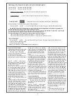
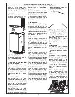
Lockout procedure
Flame disappearance :
When the ionisation electrode does not
detect flame presence. The orange indi-
cator led 

34 extinguishes. A lighting

cycle starts. If a flame is not detected,
before 10 seconds, the safety solenoids
will close. The lockout red indicator 

35

lights and the display shows the error

code. The pump runs and the 3 way
valve 

17 stays in its position. After a few

seconds, it will become possible to reset
the boiler by pressing the reset key 

36.

Overheat detection :
If an overheat (over 100°C) is detected in
the primary circuit by the sensor 23, the
safety solenoids close and the fan stops.

The orange led 

34 extinguishes and the

pump remains running  for 3 minutes.
The reset will be possible when the pri-
mary temperature will decrease under
76°C.

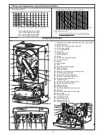
CENTORA GREEN FUNCTIONAL DIAGRAM

Heating mode

Hot water mode

40

49

48

43

41

20

39

38

37

22

19

21

23

18

17

16

14

13

12

6

3

8

15

5

7

DIAGRAM

ELECTRICAL WIRING

Содержание Centora green

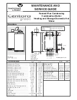
Страница 1: ...s Min operating 0 7 bar 0 7 bar C H circuit pressures Max operating 2 5 bar 2 5 bar DHW flow rates 30 C 12 l min 14 l min DHW flow rates 35 C 10 3 l min 12 l min Cold water mains pressures Min operating 0 5 bar 0 5 bar Cold water mains pressures Max operating 10 bar 10 bar Flow limiter rate 8 l min 10 l min Safety discharge 3 bar 3 bar Expansion vessel Pre charge pressure 0 7 bar 0 7 bar Net capac...

Страница 2: ...ic valves closed bar 0 1 3 4 1 2 3 4 5 6 8 11 12 13 14 7 15 10 9 16 1 Steel chassis complete with expansion vessel not visible 2 Sealed chamber 3 Burner and heat exchanger assembly 4 Air gas connection 5 24 V modulating fan 6 Gas valve 7 Ignition electrode 8 Ionisation probe 9 Ignitor 10 Combustion products manifold 11 24 V transformer 12 Siphon 13 Electrical box 14 Pump 15 Secondary heat exchange...

Страница 3: ... and the display will show the Heating flow temperature Keys 31 and 32 allow to adjust the temperature required in the Central Heating system regarding the weather conditions press to increase temperature when weather is cold press to reduce temperature when weather is fair During the temperature setting operation the display will flash If the room thermostat is calling for heat a dot will be disp...

Страница 4: ...gnites the gas As soon as a flame is detected the orange indicator led 34 will light and the regulation system will be able to adjust the gas rate regarding the heat load If a flame is not detected after 10 seconds the security solenoids close together and shut off the gas The red lockout indicator led 35 will light Press the reset button to re light the burner The domestic hot water temperature i...

Страница 5: ...in its position After a few seconds it will become possible to reset the boiler by pressing the reset key 36 Overheat detection If an overheat over 100 C is detected in the primary circuit by the sensor 23 the safety solenoids close and the fan stops The orange led 34 extinguishes and the pump remains running for 3 minutes The reset will be possible when the pri mary temperature will decrease unde...

Страница 6: ...e conditions or the configurations of the boiler Section Digit 1 Digit 2 and 3 Software version of display PCB 0 10 to 99 Flue type 2 1 FF variable speed Room thermostat is calling for heat 3 0 no 3 1 yes Theoretical position of the 3 way valve 4 0 DHW 4 1 CH DHW flow temperature in Celsius degrees 5 from 00 to 99 CH flow temperature in Celsius degrees 7 from 00 to 99 Software version of main PCB ...

Страница 7: ...d 3 Room thermostat operation 0 0 Burner only 0 1 Burner and pump Pump speed 1 0 High speed 1 1 Low speed Pump post circulation duration 2 0 0 min From 0 to 5 minutes by step of 0 5 min 2 0 5 min 2 1 0 min 2 5 0 min Maximum Central Heating flow temperature 4 50 C 4 80 C CH anti cycling delay 8 0 0 min From 0 to 7 minutes by step of 0 5 min 8 0 5 min 8 2 5 min 8 5 0 min CH maximum output limitation...

Страница 8: ...rate to maximum output set in menu 4 sec tion 9 Central heating temperature is dis played in celsius degrees The 3 dots indicate that the combus tion rate control is ON at maximum output X X Switching off the combustion rate control mode press once press once press once press once press once Effect Display Locking conditions of the combustion rate control mode boiler in stand by mode D H W draw of...

Страница 9: ... Action on burner only or pump and burner change for section 9 Adjustment of CH heat output Press on key on DHW side times The display shows 906 which corresponds to the 18 kW which is the factory setting 9 section 9 06 18 kW press on setting key on CH side one time the 2nd and 3rd digits flash together Then press on or key on DHW side to change the C H heat output step between 00 and 10 Press on ...

Страница 10: ...cated on the gas valve assembly and the different transformers in the sealed chamber Check combustion chamber insulation panels for damage Check the lighting and ionisation electrodes condition Clean the burner Never use metallic brush which can damage the stainless steel Clean the heat exchanger Never use metallic brush which can damage the stainless steel Clean the siphon and pay attention to th...

Страница 11: ...embly by loosen the two hexago nal head screws Reassemble in reverse order and replace the necessary gas kets 9 Gas section Carry out all operations mentioned in step 7 Unscrew the three screws secur ing the air gas connection pipe onto the gas valve assembly Separate the gas valve assembly and the venturi from the fan assembly by loosen the two hexago nal head screws The venturi and the gas secti...

Страница 12: ...exchanger Loosen the two screws to remove the igniter Reassemble in reverse order 22 Main control board Carry out step 1 as above and hinge down electrical box by pressing the retaining tabs P on either sides Remove wiring cover C Undo the 4 screws of the electrical rear panel and remove it Unplug all cables from the PCB remove earth plug from earth socket Hang out the main PCB Reassemble in rever...

Страница 13: ...the boiler primary circuit Ok No Replace heating thermistor Check heating thermistor Ok No No No No Yes Yes Yes No No No Ok Ok Ok Ok means a test or a choice means an action means a group of actions error code displayed PLEASE CHECK THE FOLLOWING POINTS CAREFULLY BEFORE GOING THROUGH THE FAULT FINDING CHART Gas pressure Electric mains Minimum water pressure in the heating circuit over 0 8 bar All ...

Страница 14: ...D light No Yes Replace the DHW heat exchanger Yes Yes Yes Yes No 3 Replace display PCB or control the connection between the 2 PCBs Is the combution chamber full of conden sates Yes Check ionisation probe No Ok Drain and clean combustion cham ber siphon and drain pipes Yes Replace the ionisation probe No Stop water draw off Does DHW temper ature rise over 70 C Check DHW ther mistor No Ok Press on ...

Страница 15: ...R27 R91 R89 R47 C83 C78 C80 C79 ST1 R87 Z10 Z9 Z6 Z7 Z5 Z4 Z3 Z2 Z11 Z1 U3 U10 U9 U7 U6 U4 TR1 TH2 TERRE T8 T7 T5 T4 T3 R46 T2 T6A T6 T12 T11 T10 T1 SW1 RL8 RL7A RL7 RL6 RL10 RL5A RL5 RL4A RL4 RL3A RL3 RL2A RL1A RL9 RL1 RAD1 R118 R114 R113 R111 R112 R110 R109 R108R107 R106 R9 R105 R101 R100 R99 R98 R97 R96 R8 R95 R94 R93 R92 R90 R88 R66 R65 R64 R62 R7 R58 R59 R57 R24 R52 R53 R51 R6 R50 R49 R55 R5 ...

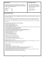
Страница 16: ...d in this document Manufacturer Chaffoteaux Maury France Commercial subsidiary MTS GB Limited MTS Building Hughenden Avenue High Wycombe Bucks HP13 5FT Telephone 01494 755600 Fax 01494 459775 Internet www chaffoteaux co uk E mail info uk mtsgroup com Technical Support Help Line 0870 241 8180 Customer Service Help Desk 0870 600 9888 This appliance is suitable for Natural gas or LPG A gas conversion...

Отзывы: