


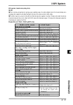


3 EFI System
3-11
3
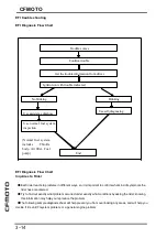
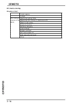
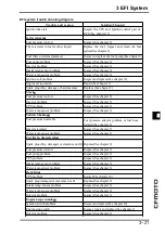
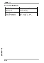
EFI trouble shooting
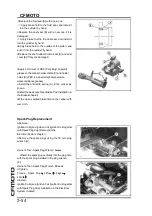
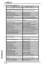
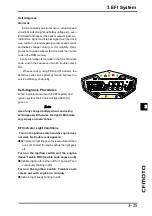
●
The DFI part connectors [A] have seals [B], in-
cluding the ECU.
●
Join the connector and insert the needle adapt-
ers [C] inside the seals [B] from behind the connec-
tor until the adapter reaches the terminal.
CAUTION
Insert the needle adapter straight along the
terminal in the connector to prevent short-
circuit between terminals.
●
Make sure that measuring points are correct in
the connector, noting the position of the lock [D] and
the lead color before measurement. Do not reverse
connections of the hand tester or a digital meter.
●
Be careful not to short-circuit the leads of the EFI
or electrical system parts by contact between
adapters.
●
Turn the ignition switch ON and measure the volt-
age with the connector joined.
CAUTION
Incorrect, reverse connection or short circuit by
needle adapters could damage the DFI or
electrical system parts.
●
After measurement, remove the needle adapters
and apply silicone sealant to the seals [A] of the
connector [B] for waterproofing.
●
Always check battery condition before replacing
the EFI parts. A fully charged battery is a must for
conducting accurate tests of the DFI system.
●
Trouble may involve one or in some cases all
items. Never replace a defective part without deter-
mining what CAUSED the problem. If the problem was
caused by some other item or items, they too must
be repaired or replaced, or the new replacement part
will soon fail again.
Содержание CF400-A 2017
Страница 1: ...WWW CFMOTO COM Service manual CF400 A CF650 7B ...
Страница 2: ...All right reserved ZHEJIANG CFMOTO POWER CO LTD Sep 2017 WWW CFMOTO COM ...
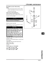
Страница 31: ...2 13 2 Periodic maintenance 2 Special tool ...
Страница 74: ...3 2 CFMOTO Exploded View ...
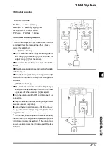
Страница 109: ...3 EFI System 3 37 3 Intake temp and pressure sensor Wiring diagram 1 ECU 2 Intake temp and pressure sensor ...
Страница 148: ...4 2 Exploded view ...
Страница 153: ...4 Cooling system 4 4 7 Special tool Bearing pressor Oil seal pressor ...
Страница 168: ...5 3 5 Engine top 5 Exploded view ...
Страница 170: ...5 5 5 Engine top 5 Exploded view ...
Страница 174: ...5 9 5 Engine top 5 Special tool and sealant ...
Страница 203: ...6 2 CFMOTO Exploded view ...
Страница 206: ...6 Clutch 6 5 6 Clutch holder Sealant Special tool and sealant ...
Страница 210: ...6 Clutch 6 9 6 Clutch Cover Disassembly Remove Oil Seal A Needle Bearings B Remove the oil level gauge A Clutch Cover ...
Страница 220: ...7 2 CFMOTO Exploded view ...
Страница 222: ...7 4 CFMOTO Engine Oil Flow Chart ...
Страница 223: ...7 Engine Lubrication system 7 5 7 Engine Oil Flow Chart ...
Страница 237: ...8 2 CFMOTO Exploded view ...
Страница 245: ...9 3 9 Crankshaft Transmission 9 Exploded view ...
Страница 247: ...9 5 9 Crankshaft Transmission 9 Exploded view ...
Страница 284: ...10 2 CFMOTO Exploded view ...
Страница 287: ...10 Tire and rim 10 10 5 Special tool Bearing pressing tool Screw driver Jack Jack accesesories Bearing remover ...
Страница 300: ...11 2 CFMOTO Exploded view ...
Страница 314: ...12 Breakingsystem 12 3 12 Exploded view Front break ...
Страница 316: ...12 Breakingsystem 12 5 12 Exploded view Rear break ...
Страница 319: ...12 8 CFMOTO Special tool Retainer plier Hand tester Jack Jack accessories ...
Страница 335: ...13 2 CFMOTO Frontfork exploded view ...
Страница 337: ...13 4 CFMOTO Rearswing armexplodedview ...
Страница 350: ...14 2 CFMOTO Exploded view ...
Страница 372: ...16 4 CFMOTO Parts location 1 2 3 4 5 6 7 8 9 10 11 12 13 14 15 16 17 18 19 20 22 21 ...
Страница 402: ...Ignition System Ignition system wiring diagram 16 34 CFMOTO ...
Страница 409: ...16 Electrical system 16 41 16 Starting system Starting system wiring ...


