SmaRT 218, 918
U053.5.1-SmaRT_OO-x18_Sys
10
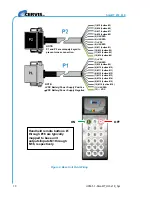
Figure 8. Base Unit Field Wiring
(8) M14 (button #14)
(9) M15 (button #15)
(10) M16 (button #16)
(11) UNUSED
(12)
— VDC
(8) UNUSED
(6) UNUSED
(5) UNUSED
(4) M8 (button #8)
(1) M5 (button #5)
(12) M4 (button #4)
(11) M3 (button #3)
(10) M2 (button #2)
(9) M1 (button #1)
(3) M7 (button #7)
(7) +VDC
(2) M6 (button #6)
(7) M13 (button #13)
(6) M12 (button #12)
(5) M11 (button #11)
(4) M10 (button #10)
(3) M9 (button #9)
(2) UNUSED
(1) +VDC
NOTE:
+VDC Battery/Power Supply Positive
−
VDC Battery/Power Supply Negative
NOTE:
P1 and P2 are uniquely keyed to
prevent cross connection.
Handheld remote buttons #1
through #16 are typically
mapped to base unit
outputs/Inputs M1 through
M16, respectively.
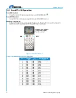
ON
OFF

