Remote Control System
©
2020 Cervis, Inc.
9
5.1
BU-X16F Base Unit Installation
During installation, make sure the machine that the base
unit will be installed on is disabled.
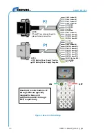
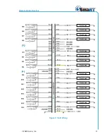
When mounting the base unit and connecting the wiring harnesses, use the configuration
diagrams Cervis, Inc. supplied as a guide. Figure 7 illustrates dimensions for drilling mounting
holes. Figure 8 illustrates the wiring harness connections.
Figure 7. Internal and External Antenna Base Unit Dimensions
36mm
(1.4")
P1
P2
118mm (4.7")
7.4mm
(0.29") dia.
1
3
3
m
m
(5
.2
5
"
)
1
1
8
m
m
(4
.7
"
)
7.4mm
(0.29") dia.
180mm (7.08")
9
0
0
MHz
A
nt
.
1
8
3
m
m
7
.2
"
102mm (4") centers
External Antenna Unit
Internal Antenna Unit
2
.4
GH
z
A
nt
.
115
m
m
4
.5
7
"

