Installation Guide
FibeAir
®
IP
-
20G
20G Assured
Doc ID: DOC-00041192 Rev E.08
June 2018
© Copyright 2018 by Ceragon Networks Ltd. All rights reserved.
Страница 1: ...Installation Guide FibeAir IP 20G FibeAir IP 20G Assured Doc ID DOC 00041192 Rev E 08 June 2018 Copyright 2018 by Ceragon Networks Ltd All rights reserved ...
Страница 2: ... Product may use open source software among them O S software released under the GPL or GPL alike license Open Source License Inasmuch that such software is being used it is released under the Open Source License accordingly The complete list of the software being used in this product including their respective license and the aforementioned public available changes is accessible at Network elemen...
Страница 3: ...spection 17 2 3 Unpacking Equipment at the Site 18 3 Installing the IP 20G IDU 19 3 1 Kits required to perform the installation 19 3 2 Tools 19 3 3 Installing the IP 20G IDU in the Rack 19 20 3 4 Grounding the IP 20G 21 3 5 Replacing an IP 20G IDU or SM Card 22 4 Connecting the Power Cable 24 4 1 Power Supply Notes 26 5 Cabling Requirements for Unit Redundancy 27 5 1 Cabling for Ethernet Interface...
Страница 4: ...ons 36 7 1 Environmental Specifications for IDU 36 7 2 Environmental Specifications for RFU 36 7 3 Mechanical Specifications 37 7 4 Power Consumption Specifications 38 8 Acceptance Commissioning Procedures 39 8 1 Site Acceptance Procedure 40 8 2 Site Acceptance Checklist Notes 44 8 3 Radio Link Commissioning Procedure 46 8 3 1 Scope 46 8 3 2 Commissioning Test 46 8 4 IP 20 Commissioning Log 47 ...
Страница 5: ...on 19 Figure 4 Power Supply Grounding 24 Figure 5 Correct Wiring of Power Connector 25 Figure 6 Connecting the Power Cable 25 Figure 7 IP 20G with Unit Redundancy Protection and Management Connection 28 Figure 8 Terminal Interface 29 Figure 9 Management Interface 30 Figure 10 Login Window 31 Figure 11 Change User Password Page 32 Figure 12 Quick Configuration From File Page 34 Figure 13 Quick Conf...
Страница 6: ...f Tables Table 1 2 x FE Splitter Cable Marketing Model 13 Table 2 Y Cable for Electrical Splitter Mode FE Traffic Interface Protection 27 Table 3 Y Cable for E1 DS1 Protection 27 Table 4 Splitter Cable for Protection and Management 28 Table 5 IDU Mechanical Specifications 37 Table 6 RFU C Mechanical Specifications 37 ...
Страница 7: ...lds Exposure to strong high frequency electromagnetic fields may cause thermal damage to personnel The eye cornea and lens is easily exposed Any unnecessary exposure is undesirable and should be avoided In radio relay communication installations ordinary setup for normal operation the general RF radiation level will be well below the safety limit In the antennas and directly in front of them the R...
Страница 8: ...al cable Before disconnecting an optical cable from the optical transmitter the power should be switched off If this is not possible the cable must be disconnected from the transmitter before it is disconnected from the receiver When the cable is reconnected it must be connected to the receiver before it is connected to the transmitter Grounding This equipment is designed to permit connection betw...
Страница 9: ...em The equipment shall be connected to a properly grounded supply system All equipment in the immediate vicinity shall be grounded the same way and shall not be grounded elsewhere Local Supply System The DC supply system is to be local i e within the same premises as the equipment Disconnect Device A disconnect device is not allowed in the grounded circuit between the DC supply source and the fram...
Страница 10: ...ion of the IP 20G IDU only Some features described in this manual may not be available in the current release Consult the Release Notes for the functionality supported in the specific release you are using Target Audience This guide is intended for use by personnel of all levels certified by Ceragon personnel such as system engineers technicians or supervisors Related Documents IP 20G Technical De...
Страница 11: ... 48V power to the RFU An IP 20G IDU contains six Ethernet interfaces one or two radio interfaces depending on the hardware configuration and optionally a 16 x E1 DS1 interface The IDU also includes two FE management interfaces a DB9 dry contact external alarms interface an RJ 45 synchronization interface and an RJ 45 terminal console interface for connection to a local craft terminal IP 20G receiv...
Страница 12: ...et traffic interfaces 2 x GE dual mode electrical or cascading interfaces RJ 45 GbE1 CS1 GbE2 CS2 2 x GE electrical interfaces RJ 45 GbE3 GbE4 2 x GE optical interfaces SFP SFP5 SFP6 Important Note When using electrical ports GbE 1 through GbE 4 to connect between the IP 20G IDU and an outdoor unit such as IP 20C or IP 20S in areas in which severe lightning conditions are likely to occur it is req...
Страница 13: ...Connections 1 2 1 Management Interface Cable Options If the user only needs to use a single management interface a standard Cat5 RJ 45 cable straight or cross can be connected to the MGMT interface To access both management interfaces a special 2 x FE splitter cable can be ordered from Ceragon Table 1 2 x FE Splitter Cable Marketing Model Marketing Model Marketing Description Part Number SPL ETH C...
Страница 14: ...es an external supply of 48V current via one or two power interfaces the second power interface is optional for power redundancy The IP 20G monitors the power supply for under voltage and includes reverse polarity protection so that if the positive and negative inputs are mixed up the system remains shutdown The allowed power input range for the IP 20G is 40V to 60V An under voltage alarm is trigg...
Страница 15: ...ernal Alarms IP 20G includes a DB9 dry contact external alarms interface The external alarms interface supports five input alarms and a single output alarm The input alarms are configurable according to 1 Intermediate 2 Critical 3 Major 4 Minor 5 Warning The output alarm is configured according to predefined categories ...
Страница 16: ...tion FIPS 197 over radio links The FibeAir IP 20 Assured platform also provides Secured communication and protocols for management interface Centralized user authentication management via RADIUS Advanced identity management and password policy enforcement Security events log Secure product architecture and development The following products are included in the FibeAir IP 20 Assured platform FibeAi...
Страница 17: ...ngs The cargo must be kept dry during transport and storage For sea transport deck side shipment is not permitted Carrier owned cargo containers should be used It is recommended that the equipment is transported to the installation site in its original packing cases If any intermediate storing is required all cases must be stored under dry and cool conditions and out of direct sunlight 2 2 Inspect...
Страница 18: ...It is essential that whenever unpacking or disassembling the equipment and handling printed circuit boards special precautions should be taken to avoid ESD Electrostatic Static Discharge Generally units with static discharge protection should not be unpacked until the installation takes place Ensure you are properly grounded at a controlled ESD point before and during unpacking and handling of any...
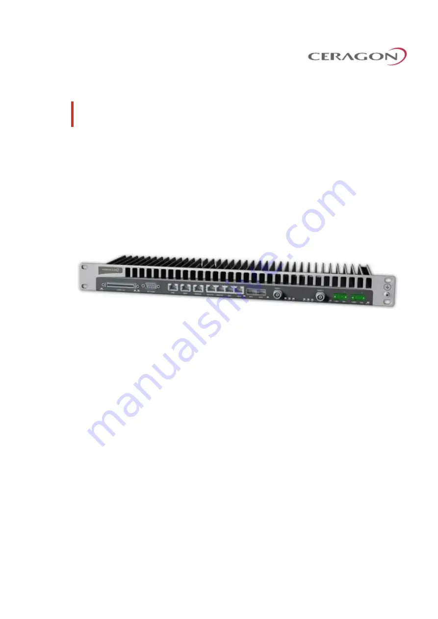
Страница 19: ...idential 3 Installing the IP 20G IDU This section provides instructions for installing a FibeAir IP 20G IDU Figure 3 IDU Full Configuration 3 1 Kits required to perform the installation Description Quantity IP 20G chassis 1 19 rack sub rack 1 SM Card Cover 1 3 2 Tools Philips screwdriver Flat screwdriver ...
Страница 20: ...20G IDU in the rack as shown in the following figures Use four screws not supplied with the installation kit to fasten the IDU to the rack If you are installing multiple IP 20G units in a single rack make sure to leave a space of 1RU after every two IP 20G units as shown in the figure below This restriction also applies to IP 20G units installed in proximity with third party units ...
Страница 21: ...rietary and Confidential 3 4 Grounding the IP 20G Connect a grounding wire first to the single point stud shown in the figure below and then to the rack using a single screw and two washers Verify that the grounding resistance is 0 2 ohms Note The grounding wire must be 16 AWG or thicker ...
Страница 22: ... is embedded in the SM Card Cover so re using the existing SM Card Cover is necessary to ensure that the unit s software and configuration is maintained In some cases you may need to replace the SM Card itself in order to upgrade the unit s configuration To remove the SM Card Cover 1 Switch the unit power off 2 Loosen the screws of the SM Card Cover and remove it from the IDU 3 In the new IDU or i...
Страница 23: ...allation Guide for FibeAir IP 20G FibeAir IP 20G Assured Page 23 of 49 Ceragon Proprietary and Confidential 4 Gently place the SM Card Cover in its place and tighten the screws using a Phillips screwdriver ...
Страница 24: ...ingle feed power interface Optionally IP 20G can be ordered with a second power interface for power redundancy A power cable connector is included with the IP 20G unit The following power cables are available for use with an IP 20G unit Ceragon Part Number Marketing Model Marketing Description WA 0567 0 CBL PWR OE OE 16A 2 2m Power cable Open end Open end 16A 2 2m WA 0568 0 CBL PWR OE OE 16A 5m Po...
Страница 25: ...ntial Figure 5 Correct Wiring of Power Connector 4 Insert the wires into the connector 5 Secure the wires in the connector with the screws 6 Plug the connector into the IP 20G power interface and tighten the two screws on the sides of the connector to secure the connector Figure 6 Connecting the Power Cable ...
Страница 26: ...attery backup and emergency power generator The power source must be grounded The unit has more than one supply connection Remove all power from the unit for servicing Important Make sure to use a circuit breaker to protect the circuit from damage by short or overload In a building installation the circuit breaker shall be readily accessible and incorporated external to the equipment The maximum r...
Страница 27: ...45F TO 2XRJ45 1 34M CAT 5E No special cabling is required for other Ethernet protection modes 5 2 Cabling for E1 DS1 Interfaces If the E1 DS1 interfaces are being used a Y cable is used to connect the active and standby E1 DS1 interfaces The following table shows the Part Number and Marketing Model of the Y cable required for E1 DS1 protection Table 3 Y Cable for E1 DS1 Protection Part Number Mark...
Страница 28: ... and Management Part Number Marketing Model Description WA 0720 0 CBL IP20 EXT PROT MGMT CABLE RJ45F TO 2XRJ45 1 34M CAT 5E WITH MALE TO MALE CONNECTION The protection and management splitter cable must be connected to the management interfaces of the two IP 20G units using the RJ 45 plug ends The third end of the protection splitter cable RJ 45 socket is connected to an external management statio...
Страница 29: ...de for Chassis Based Systems FibeAir IP 20N IP 20A IP 20LH and Evolution IP 20LH 6 1 Establishing a Connection You can connect to the IP 20G unit using a TP cable with a LAN connection or using a Serial RS 232 cable 6 1 1 Connecting to the Unit with a Serial Connection 1 Connect an RS 232 cable with an RJ 45 interface from your laptop or PC to the Terminal Interface on the IP 20G front panel Figur...
Страница 30: ...the PC and the IP 20G unit it is necessary to have an IP address on the PC within the same subnet as the unit The default IP address of the IP 20G unit is 192 168 1 1 Set the PC address to e g 192 168 1 10 and subnet mask to 255 255 255 0 Note the initial settings before changing Note The chassis IP address as well as password should be changed before the system is set in operation For more inform...
Страница 31: ...ragon Proprietary and Confidential 6 2 Logging On 1 Open an Internet browser Internet Explorer or Mozilla Firefox 2 Type in the default IP address 192 168 1 1 in the Address Bar Figure 10 Login Window 3 Enter the following values o User Name admin o Password admin 4 Click Apply ...
Страница 32: ...Strength is activated the password must meet the following criteria o Password length must be at least eight characters o Password must include characters of at least three of the following character types lower case letters upper case letters digits and special characters For purposes of meeting this requirement upper case letters at the beginning of the password and digits at the end of the pass...
Страница 33: ...e of the hop may be lost By default all elements have the same IP settings IP address 192 168 1 1 Subnet mask 255 255 255 0 Note After the new IP address is set the contact with the element will be lost In order to reconnect the PC must have an IP address within the same subnet as the element In addition to setting the IP addresses the following configuration steps should be performed in order to ...
Страница 34: ...n Global Services and provided as a service The pre defined configuration file must be compatible with the CeraOS version the IP 20 device is running Configuration files created for CeraOS 9 2 cannot be used with CeraOS 9 2 5 or higher Configuration files must also be compatible with the type of IP 20 device For example a configuration file created for IP 20GX cannot be applied to an IP 20G device...
Страница 35: ...configuration click Submit Progress is updated in the Quick Configuration From File page When the configuration is complete the unit reboots If the configuration file includes changing from ETSI to ANSI mode the unit reboots at that point in the configuration After the reboot you must return to the Quick Configuration From File page and re initiate the configuration Note If the pre defined configu...
Страница 36: ...lity o 25 C 13 F to 65 C 149 F Temperature range for exceptional temperatures tested successfully with limited margins Note Cold startup requires at least 5 C 23 F Humidity 5 RH to 95 RH 7 2 Environmental Specifications for RFU Operating ETSI EN 300 019 1 4 Class 4 1 Temperature o 33 C 27 F to 55 C 131 F Temperature range for continuous operating temperature with high reliability o 45 C 49 F to 60...
Страница 37: ...Width 426 mm 16 77 Depth 180 mm 7 08 Weight 2 5 kg 5 5 lbs IDU RFU Connection Coaxial cable RG 223 300 ft Belden 9914 RG 8 1000 ft or equivalent TNC connectors to the IDU N type connectors male to the RFU Table 6 RFU C Mechanical Specifications RFU C Dimensions Height 200 mm 7 87 Width 200 mm 7 87 Depth 85 mm 3 35 Weight 4kg 9 lbs RFU C Standard Mounting OD Pole 50 mm 120 mm 2 4 5 subject to vendo...
Страница 38: ...ble shows the maximum power consumption for IP 20G IDU and supported RFUs The maximum power consumption for the entire system is the sum of the IDU and the RFUs connecting to it Configuration Power W Comments IDU Eth only with single RFU 23 5W Addition for second RFU 2 9W Addition for 16 E1s 11W RFU C 6 26 GHz 1 0 22 1 1 39 RFU only 28 38 GHz 1 0 26 1 1 43 RFU only ...
Страница 39: ...dure is to verify correct installation and operation of the installed link and the interoperability with customer end equipment Ceragon s Acceptance and Commissioning procedure includes the following stages Site Acceptance Procedure Commissioning of radio link The Site Acceptance Procedure is a checklist that summarizes the installation requirements of the site at which the products were installed...
Страница 40: ... ANTENNA MOUNTING Antenna mount type Mount is of sufficient height to clear local obstructions OK Mount is safely positioned to not cause a safety hazard OK Mount is secure and perpendicular OK Mount is grounded as per site specifications OK All steelwork is Galvanized or Stainless Steel as appropriate OK 3 ANTENNA Antenna type model and size Antenna is securely fixed to mount OK Antenna is ground...
Страница 41: ...bolts are secured using washers and lock washers as appropriate OK Flexible waveguide is secured to the pole OK 6 COAX CABLE Overall cable length Cable type N Type connectors assembled properly on the cable OK Cable connected securely to RFU and IDU OK Cable connector is weather proofed sealed at the RFU OK At the RFU cable has a service drip loop to prevent moisture from entering the connector OK...
Страница 42: ...ble WG ends are properly labeled OK 8 INDOOR UNIT IDU is securely mounted to the rack OK IDU is located in a properly ventilated environment OK IDU fans are functional and air flow to the fans is not disrupted OK IDU and rack are grounded as per site specifications OK Traffic cables and connections are properly terminated as per manufacturer cable instructions OK All cabling is secured tidy and vi...
Страница 43: ...r IP 20G Assured Page 43 of 49 Ceragon Proprietary and Confidential SITE ACCEPTANCE CHECKLIST continued 11 REMARKS NOTES 12 GENERAL INFORMATION Site accepted by Name Title Company Signature Date Site approved by Name Title Company Signature Date ...
Страница 44: ...45 degree cone of protection of existing lightning conductors additional lightning protectors should be installed All steelwork is Galvanized or Stainless Steel as appropriate to prevent corrosion 2 Antenna Antenna is grounded as per site specifications See the third point in the Antenna Mounting section above Antenna sway braces are fitted and installed correctly where applicable Typically for an...
Страница 45: ...nations are secure and correctly terminated All labeling is complete as per site requirements Labeling is specific to each customer At a site with only one installation labeling may be unnecessary However at sites with multiple installations correct and adequate labeling is essential for future maintenance operations Typical labeling requirements include Antenna labels for link identity and bearin...
Страница 46: ...acket Loss test for at least one hour load rate as per Ceragon s specifications for the chosen MRMC Connect Ethernet Packet Analyzer to the FE port Use physical loop at remote end or connect second analyzer Run Packet Loss test for at least one hour load rate as per Ceragon s specifications for the chosen MRMC Interoperability Verification Connect customer end equipment to the line interfaces and ...
Страница 47: ...ecommended commissioning tests Maintaining the Commissioning Log is important for tracking your installations and to provide essential data for Ceragon Networks Upon completing the Commissioning Log send the log to Ceragon support center at support ceragon com IP 20 LINK COMMISSIONING LOG 1 GENERAL INFORMATION Customer Radio model Configuration Radio link code Site 1 name add Site 2 name add 2 RFU...
Страница 48: ...sses 4 LINK PARAMETERS Site 1 Site 2 Link distance Rain zone Expected RSL dBm Expected Diversity RSL dBm RSL Main dBm RSL Diversity dBm Deviation from exp RSL 4 dB 5 COMMISSIONING TESTS Site 1 Site 2 Line loopback Pass Pass RFU loopback Pass Pass Radio BER Pass Pass FE test Pass Pass GbE test Pass Pass 6 MANAGEMENT CONFIGURATION Site 1 Site 2 Eth IP Address Eth IP mask Default router In band VLAN ...
Страница 49: ...n Guide for FibeAir IP 20G FibeAir IP 20G Assured Page 49 of 49 Ceragon Proprietary and Confidential 8 INSTALLATION INFORMATION Installed by Name Company Date Signature Commissioned by Name Company Date Signature ...