Installation Preparation
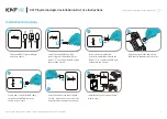
Installing the MP412 is easy as long as you do a little planning before starting. Locate the unit within ten feet of an a. c. power outlet and seven feet of
the telephone jacks. The maximum amount of telephone wire that can be between the unit any station is 600 feet. The MP412 has been assigned the
station number 22. Any NSQ412 that uses this station number will have to be changed to another number.
IMPORTANT:
Taking full advantage of the system features requires that the telephone number connected to Line 1 be the same on all stations. If this
is not done, the Page will not work properly. In addition, it is strongly recommended that no other devices operate on Line 1 or Line 2 besides the
NSQ412 stations and the MP412. Any interference on it can degrade the system performance. The system can be used on a DLS line if either: 1)
Line 1 is not the DSL line; or 2) Line 1 wiring connected to all stations is behind the DSL filter port.
CAUTION!
1. Never install telephone jacks during a lightning storm.
2. Never install telephone jacks in wet locations unless the jack is specifically designed for wet locations.
3. Never touch uninsulated telephone wires or terminals unless the telephone line has been disconnected at the network interface.
4. Use caution when installing or modifying telephone lines.
5. Always disconnect all telephone lines from the wall outlet before servicing or disassembling this equipment.
6. Danger of explosion if battery is incorrectly replaced.
Installing the Unit on a Desk or Table
NOTE:
Do not connect the a. c. power adapter until instructed to do so.
The following instructions show how to connect four telephone lines to the MP412. As few as one line can be connected.
1. Carefully remove all of the unit components from their packing.
2. If telephone lines 1 and 2 are on one jack and telephone lines 3 and 4 are on another jack, see the following connection drawing. Otherwise, go to
step 3.
Connect telephone jack 1 to the MP412 L1/L2 jack using one of the 4-conductor telephone line cords supplied with the unit. Connect telephone
jack 2 to the MP412 L3/L4 jack using the other 4-conductor telephone line cord supplied with the unit.
5
GETTING STARTED
Key and Indicator Descriptions
The following drawings provide identification and brief descriptions of the control and indicator.
Power & Paging LED: Illuminates continuously for power, flashes to indicate paging or another NSQ412 has the same extension number.
Audio Out Jack: Used to provide the MP412 page signal to an external paging amplifier and speaker.
Audio In Jack: Used to connect an external music source for music on hold.
Line Jacks: Jack L1/L2 is used for telephone lines 1 and 2. Jack L3/L4 is used for telephone lines 3 and 4
Paging Volume Knob: Adjusts the paging level.
Power Jack: The jack for connecting the a. c. power adapter to the unit.
4
INTRODUCTION
MP412 Manual_rev.qxd 6/15/05 12:23 PM Page 6


