background image

Page 8

SKU 96364

For technical questions, please call 1-800-444-3353.

INSPECTION, MAINTENANCE, AND CLEANING

1. 

WARNING!  Make sure that the tool is unplugged from the air supply before 

performing any inspection, maintenance, or cleaning procedures.

2. 

BEFORE EACH USE, inspect the general condition of the tool.  Check for loose 

screws, misalignment or binding of moving parts, cracked or broken parts, damaged 

air hose, and any other condition that may affect its safe operation.  If abnormal 

noise or vibration occurs, have the problem corrected before further use.  Do not 

use damaged equipment.

3. 

Inspect the air supply screen located in the Air Inlet (72) before each use and re-

place as needed.  Dirt and water in the air supply screen are primary causes of 

pneumatic tool wear.  Use a filter in the compressed air system for better perfor-

mance and longer tool life.  The filter must provide adequate flow capacity for the 

given application.

4. 

Clean the external parts of the Brad Nailer with a clean cloth and mild detergent.

5. 

When storing, lock the Brad Nailer in a clean, dry location, safely out of the reach 

of children. 

6. 

All maintenance, service or repairs not listed in this manual should only be completed 

by a qualified service technician.

TROUBLESHOOTING

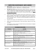
Problem

Solution

Air leak near top of tool.

1.  Tighten all screws on the cylinder cover.  

2.  Have a qualified service technician service the tool.

Tool does not work.  

1.  Make sure the compressor is set between 50-120 PSI.  

2.  Check all air connections for leaks.  

3.  Make sure Driver Guide is fully depressed on workpiece when trying 

to fire a Brad.  

4.  Have the Brad Nailer checked by a qualified service technician.

Sluggish operation.

1.  Make sure compressor regulator is set between 50-120 PSI.  

2.  Check all air connections for leaks.  

3.  Have a qualified service technician install a head valve piston set.

Air leak near bottom of tool.

1.  Tighten all screws.  

2.  Have a qualified service technician replace the bumper or install a 

head valve piston set.

Poor return after firing tool.

1.  Have a qualified service technician clean the interior of the tool or 

replace the bumper or head valve piston set.

Weak driving force.

1.  Make sure compressor regulator is set between 50-120 PSI.  

2.  Check all air connections for leaks.  

3.  Have a qualified service technician clean the interior of the tool and/

or install the head valve piston set.

Содержание 96364

Страница 1: ...s Blvd Camarillo CA 93011 Visit our website at http www harborfreight com TO PREVENT SERIOUS INJURY READ AND UNDERSTAND ALL WARNINGS AND INSTRUCTIONS BEFORE USE Copyright 2007 by Harbor Freight Tools All rights reserved No portion of this manual or any artwork contained herein may be reproduced in any shape or form without the express written consent of Harbor Freight Tools For technical questions...

Страница 2: ...l need this manual for the safety warnings and precautions assembly oper ating inspection maintenance and cleaning procedures parts list and assembly diagram Keep your invoice with this manual Write the invoice number on the inside of the front cover Write the product s serial number in the back of the manual near the assembly dia gram or write month and year of purchase if product has no number K...

Страница 3: ...ables better control of the power tool in unexpected situations 8 Use safety equipment Always wear ANSI approved eye protection Dust mask nonskid safety shoes hard hat or hearing protection must be used for appropriate conditions Always wear ANSI approved safety goggles and a dust mask respirator when using performing maintenance or reloading this tool TOOL USE AND CARE 1 Use clamps not included o...

Страница 4: ...result in a risk of injury 2 When servicing a tool use only identical replacement parts Follow instruc tions in the Inspection Maintenance And Cleaning section of this manual Use of unauthorized parts or failure to follow maintenance instructions may create a risk of electric shock or injury SPECIFIC SAFETY RULES 1 Maintain labels and nameplates on the tool These carry important information If unr...

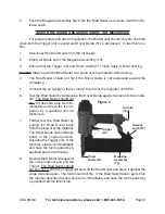
Страница 5: ...ed to the Brad Nailer See Figure 1 2 Wrap the 1 4 air connector not included with at least four turns of pipe thread seal tape before connecting to a 3 8 ID Air Source Hose not included 3 Set the air pressure on the compressor between 50 to 120 PSI The recommended setting is 90 PSI Do not exceed the maximum air pressure of 120 PSI The amount of air pressure used effects how deep the Brads will be ...

Страница 6: ...he regulator at 90 PSI 6 Test the Brad Nailer by depressing the Driver Guide against a piece of scrap mate rial The Brad Nailer should not fire If it does fire stop work im mediately and have the tool re paired by a qualified service technician 7 Further test the Brad Nailer by pulling the Brad Nailer back from the piece of scrap material The Driver Guide should always return to the original posit...

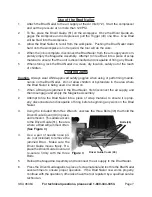
Страница 7: ...he Brad Nailer Do not allow children or bystanders in the area where the Brad Nailer is being used or worked on 1 When a Brad gets jammed in the Brad Nailer first disconnect the air supply and then disengage and empty the Magazine Assembly 2 Attempt to fire the Brad Nailer into a piece of scrap material to ensure it is prop erly disconnected and incapable of firing before beginning any work on the...

Страница 8: ... out of the reach of children 6 All maintenance service or repairs not listed in this manual should only be completed by a qualified service technician TROUBLESHOOTING Problem Solution Air leak near top of tool 1 Tighten all screws on the cylinder cover 2 Have a qualified service technician service the tool Tool does not work 1 Make sure the compressor is set between 50 120 PSI 2 Check all air con...

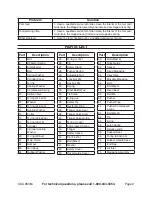
Страница 9: ...2 6x2 35 17 O ring 30x1 8 18 Cylinder 19 Cylinder Sealing Washer 20 O ring 20 5x2 21 Main Piston 22 Bumper 23 Gun Body 24 Rubber Washer Part Description 25 O ring 1 7x2 26 Pin 27 Safety Stand 28 Pusher Spring 29 Adjustable Nut 30 Lock Nut M4 31 Hex Nut M4 32 Spring 33 Steel Ball DW 2 34 Tip Stand 35 E ring d 6 36 Safety Tip 37 Rectangle Ring 38 Trigger Valve Seat 39 Trigger Valve Stem 40 Trigger V...

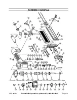
Страница 10: ...Page 10 SKU 96364 For technical questions please call 1 800 444 3353 ASSEMBLY DIAGRAM ...

Страница 11: ...90 days from the date of purchase This warranty does not apply to damage due directly or indirectly to misuse abuse negligence or accidents repairs or alterations outside our facilities criminal ac tivity improper installation normal wear and tear or to lack of maintenance We shall in no event be liable for death injuries to persons or property or for incidental contingent special or consequential...

Отзывы: