Page 6
SKU 47211
for technical questions, please call 1-800-444-3353.
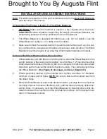
INsTALLATION ANd AssEMBLy INsTRuCTIONs
Note: For additional references to the parts listed below, refer to the Assembly diagrams
near the end of this manual.
To determine The proper Location for The Wheel Balancer:
WARNINg: Make sure this machine is used on a dry, oil/grease free, flat, level,
CONCRETE surface capable of supporting the weight of the Wheel Balancer, the
wheel being balanced, and any additional tools and equipment.
The Wheel Balancer is designed for indoors use only. Do not install or use the
Wheel Balancer outdoors, or in damp or wet locations.
Make sure to check the desired location for possible obstructions such as a low ceil-
ing, overhead lines, adequate working area, access ways, exits, etcetera. The Wheel
Balancer should be located in an area free of flammable materials and liquids.
To Mount The Wheel Balancer On A floor surface:
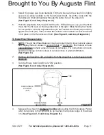
With assistance, and with the use of a lifting device, stand the Wheel Balancer in its
upright position in the desired work location. Use the three, 1/2” machine mounting
holes located at the base of the Body (501) as a template to mark the points where
three floor anchor holes will be drilled in the floor surface. Then, temporarily remove
the Wheel Balancer.
(see figure B, next page, and Assy. diagram d.)
Where previously marked on the concrete floor surface, drill three 1/2” diameter,
minimum 4” deep, anchor holes.
NOTE: Be sure to blow out the cement dust from
the drilled holes.
Move the Wheel Balancer back to the desired location, and align the three machine
mounting holes at the base of the Body (501) with the three previously drilled floor
anchor holes. If necessary, level the Wheel Balancer by inserting steel shims be-
tween the base of the machine and the concrete floor surface. Do not exceed more
than 1/2” thickness of shims.
1.
2.
3.
1.
2.
3.
Brought to You By Augusta Flint


