background image

Page 2

SKU 47211

for technical questions, please call 1-800-444-3353.

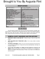
spECIfICATIONs

Electrical Requirements

220 V / 60 Hz / Single Phase
220 Volt Electrical Power Cord Plug (Not Provided)

Product Compatibility

For Most Passenger Car And Light Truck Wheels

Maximum Tire Diameter Capacity

31.5”

Maximum Tire Width Capacity

20”

Minimum/Maximum Rim Diameter Capacity 10” - 24”
Minimum/Maximum Rim Width Capacity

1.5” – 20”

Maximum Tire/Rim Weight Capacity

143 Pounds

Balancing Speed

200 RPM

Tire/Rim Balancing Modes

Normal, ALU1, ALU2, ALU3, Static

Cycle Time

10 Seconds

Type of Data Entry

Keypad w/L.E.D. Display Indicators

Self-Calibrating Function

Semi-Automatic, User-Assisted Data Entry
(1

st

 Set-Up, Or When Desired)

Automatic Start Feature

Starts When Safety Guard Is Closed

Brake Type

Automatic

Wheel Stops

At Top

Weight/Length Selections

Ounce And Gram / Inch And Millimeter

Balancing Accuracy

.035 Ounce (1 Gram)

Overall Dimensions

52” W x 40” L x 65” H (Safety Guard Open)
52” W x 38” L x 50-1/4” H (Safety Guard Closed)

Weight

265 Pounds

save this Manual

You will need this manual for the safety warnings and precautions, assembly, oper-

ating, inspection, maintenance and cleaning procedures, parts list and assembly diagram.  
Keep your invoice with this manual.  Write the invoice number on the inside of the front 
cover.  Keep this manual and invoice in a safe and dry place for future reference.

gENERAL sAfETy WARNINgs ANd pRECAuTIONs

KEEp WORK AREA CLEAN ANd dRy.  Cluttered, damp, or wet work areas invite 
injuries.

KEEp CHILdREN AWAy fROM WORK AREA.  Do not allow children to handle 
this product.

sTORE IdLE EQuIpMENT.  When not in use, tools and equipment should be stored 
in a dry location to inhibit rust.  Always lock up tools and equipment, and keep out 
of reach of children.

dO NOT usE THIs pROduCT If uNdER THE INfLuENCE Of ALCOHOL OR 
dRugs.  
Read warning labels on prescriptions to determine if your judgement or 
reflexes are impaired while taking drugs.  If there is any doubt, do not attempt to 
use this product.

1.

2.

3.

4.

Brought to You By Augusta Flint

Содержание 47211

Страница 1: ...t http www harborfreight com To prevent serious injury read and understand all warnings and instructions before use Copyright 2005 by Harbor Freight Tools All rights reserved No portion of this manual...

Страница 2: ...ons 52 W x 40 L x 65 H Safety Guard Open 52 W x 38 L x 50 1 4 H Safety Guard Closed Weight 265 Pounds Save this Manual You will need this manual for the safety warnings and precautions assembly oper a...

Страница 3: ...nly identical replacement parts Only use accessories intended for use with this product Ap proved accessories are available from Harbor Freight Tools MAINTAIN THIS PRODUCT WITH CARE Keep this product...

Страница 4: ...EEL COMES TO A COMPLETE STOP See Figure E ALWAYS KEEP HANDS FINGERS AND FEET AWAY FROMTHE MOVING PARTS OFTHE WHEEL BALANCER WHILETHE MACHINE IS IN USE Remain clear of the spinning wheel while it is be...

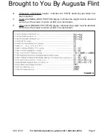
Страница 5: ...ge drop to five volts at 150 of the rated amperes IF AN EXTENSION CORD not provided IS USED MAKE SURETO USE ONLY UL APPROVED CORDS HAVING THE CORRECT GAUGE AND LENGTH See Table A ALWAYS UNPLUGTHE WHEE...

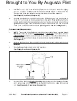
Страница 6: ...ble materials and liquids To Mount The Wheel Balancer On A Floor Surface With assistance and with the use of a lifting device stand the Wheel Balancer in its upright position in the desired work locat...

Страница 7: ...e rear mounting hole of the Shaft Then secure the Sheath to the Shaft using the Screw 107 See Assy Diagram B Slide the mounting hole of the Safety Guard 504 onto the Shaft 108 Make sure to position th...

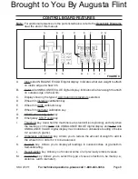
Страница 8: ...eel rim diameter calibration key START measuring cycle key Emergency STOP cycle key Threshold key Use when the machine is at a standstill not spinning and only when the readings on the Inner side UNBA...

Страница 9: ...e has been selected Outer side UNBALANCE POSITION display Indicates the weight must be attached at the top of the wheel rim when all LED s are illuminated Inner side UNBALANCE POSITION display Indicat...

Страница 10: ...ole 220 volt electrical receptacle See Assy Diagram E SAFETY GUARD 504 POWER SWITCH 523 RIM DISTANCE POINTER 202 FLANGE 23 TRANSMISSION SHAFT 24 CONE 18 THUMB LOCK ADJUSTABLE NUT 16 INNER SIDE OUTER S...

Страница 11: ...ansmission Shaft See Figure E and Assy Diagram A To Make Wheel Measurements NOTE Though the Wheel Balancer may be programmed to input numeric values and display numeric values in ounces inches or gram...

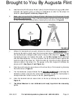
Страница 12: ...on the wheel rim NOTE If the manufacturer does not indicate the width use the Rim Caliper that is provided with the Wheel Balancer To do so position one tip of the Rim Caliper against the top inner ed...

Страница 13: ...d to the inner side of the wheel rim If all the LED s are illuminated in Display P the weight must be attached at the top of the vertical axis of the wheel rim If not all LED s are illuminated manuall...

Страница 14: ...se the keys C and START Then de press the START key only and immediately release pressure on the START key to begin the first cycle of self calibration See Figures C and D At the end of the first cycl...

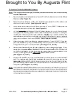
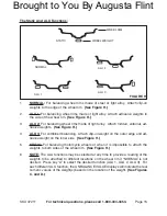
Страница 15: ...igure H ALU 3 For combined balancing Attach clip on weight on the outer edge and ad hesive weight on the inner side See Figure H STATIC For balancing motorcycle wheels or when it is impossible to atta...

Страница 16: ...n refitting Then temporarily remove wheel from the Wheel Balancer deflate the tire and use a tire remover not provided to rotate the tire 180 degrees on the wheel rim See Assy Diagram A Inflate the ti...

Страница 17: ...and backward To tighten the tension move the Motor backward until the Pulley Belt is tight to the touch and retighten the four Nuts To replace the Pulley Belt move the Motor forward toward the Pulley...

Страница 18: ...1 205 Plastic Bushing 2 206 Seeger Ring 2 207 Spring 1 208 Rim Distance Gauge 1 301 Display Panel Support 1 302 Cable RVB 300 500 1 303 Screw M5 x 16 3 304 Nut M4 8 305 Screw M4 x 28 4 306 Plastic Co...

Страница 19: ...upport 1 415 Fuse DM5X20 2A 2 501 Body 1 502 Screw M12 x 120 2 503 Washer 2 504 Safety Guard 1 505 Screw M5 x 15 4 506 Tool Tray 1 507 Plate 1 Part Description Q ty 508 Screw M5 x 7 2 509 Washer 2 510...

Страница 20: ...Page 20 SKU 47211 For technical questions please call 1 800 444 3353 ASSEMBLY DIAGRAM A 18a 18b 18c 18d 07h Brought to You By Augusta Flint...

Страница 21: ...Page 21 SKU 47211 For technical questions please call 1 800 444 3353 ASSEMBLY DIAGRAM B Brought to You By Augusta Flint...

Страница 22: ...Page 22 SKU 47211 For technical questions please call 1 800 444 3353 ASSEMBLY DIAGRAM C Brought to You By Augusta Flint...

Страница 23: ...Page 23 SKU 47211 For technical questions please call 1 800 444 3353 ASSEMBLY DIAGRAM D Brought to You By Augusta Flint...

Страница 24: ...Page 24 SKU 47211 For technical questions please call 1 800 444 3353 ASSEMBLY DIAGRAM E Brought to You By Augusta Flint...

Отзывы:

Похожие инструкции для 47211