SKU 39955
For technical questions, please call 1-800-444-3353.
Page 6
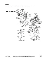
Table to Column
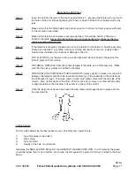
Step 1)
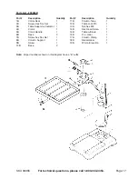
Locate the Elevation Worm Gear Shaft (part #19B), the Crank Handle (part #5B) and the
Table Crank (part #4B). Insert the Elevation Worm Gear Shaft into the Table Support and
extend the Shaft through the opening as far as possible.
Step 2)
Locate the Table Crank (part #4B). The Crank is to be installed on the Elevation Worm Gear
Shaft (part #19B). A Set Screw (part #7B) is to be aligned with the flat portion of the Shaft.
Get the Crank as close as possible to the Support, and then tighten the Set Screw.
(See Figure 1).
Step 3)
Screw the Crank handle into the Table Crank. Use an adjustable wrench to tighten the Crank
Handle securely.
Step 4)
Loosen the Set Screw (part #2B) in the Column Collar (part #1B) with the 3mm Hex wrench
and remove the Collar and Rack from the Column.
Step 5)
Locate the Rack (part #6B) and with the smooth end of the Rack pointing upward, slide it
down through the large, round opening in the Table Support (part #3B). Engage the Rack into
the Gear Mechanism found on the inside opening of the Table Support (See Figure 2 below).
Step 6)
While holding the Rack and the Table Support as assembled, slide both down over the Col-
umn. Slide the Rack down until the Rack is positioned against the lower Column Support.
Step 7)
Replace the Collar (part #1B), with the bevel side down, which was removed in Step 4.
Tighten it with the Hex wrench used in Step 4.
Note:
In order for the Rack to slide when the Table is swung to the left or right on the Column, the
Collar must sit loosely over the Rack. Only tighten the Set Screw enough to keep the Collar
in place. Over tightening the Set Screw may result in breaking of the Collar.
Step 8)
Check the Column Collar for proper adjustment. The Collar should sit evenly on the Column
and the Rack should slide freely when the Table is rotated 360 degrees.
Figure 1
Figure 2

