Cembre LD-16B Скачать руководство пользователя страница 29

29

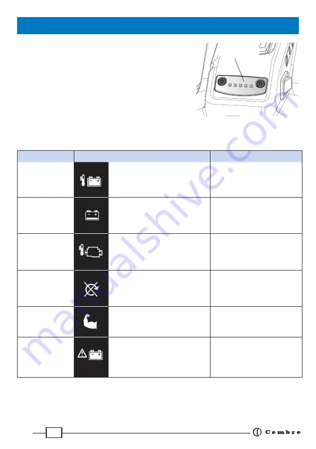
The alarms associated with a visual indication on the LED indicator 

go off  during operation of the drill and cause electronic blocking 

of the drill with a subsequent motor shut-off .

Verifi able alarms are summarised in the following table:

LED colour

Alarm description

Solution

Flashing 

RED 

Overheating of the battery caused 
by intensive use or high ambient 
temperature.

Replace the battery and wait for 
it to cool down (*).

Flashing 
YELLOW

Low battery.

Push the start switch to OFF posi-
tion, replace the battery.

Flashing 

BLUE

Overheating of the motor caused 
by intensive use or high ambient 
temperature.

Push the start switch to OFF 
position and wait for motor to 
cool down.

Flashing 

YELLOW - RED


Rotation is obstructed, blocked spin-
dle (for example blocked broach cutter 
in the rail, gears broken).

Push the start switch to OFF posi-
tion, remove what is blocking the 
spindle’s rotation and re-start 
the drill.

Constant 

RED


Exceeding maximum motor current 
absorption within a specifi c time.

Push the start switch to OFF posi-
tion, re-start the drill.
Lighten the force on the spindle
lever.

Constant 

YELLOW

- Power supply failure; insertion of 
   the battery with the start switch in 
   ON position.
- Self diagnosis with a negative out
   come.

- Push the start switch to the OFF 
  position, re-start the drill.

- If the problem persists, please  
  contact 

Cembre

.

(*)   If the battery overheats, it is possible to insert it into the supplied battery charger, making use of the specifi c 


“AIR COOLED” function in order to make it cool down quicker.

13. ALARMS

LED indicator

Содержание LD-16B

Страница 1: ...1 RAIL DRILL LD 16B LD 16BA LD 16BE LD 16BT ENGLISH D K D Y D OPERATION AND MAINTENANCE MANUAL 16 M 187 E...

Страница 2: ...sembling broach cutters with Quick push turn shank 19 11 2 Assembling broach cutters with Weldon shank 20 11 3 Assembling spiral bits 21 11 4 Assembling terminations on DBG F2 clamping device 22 11 5...

Страница 3: ...d wearing clothes which may present a risk to personal safety The degree of protection of the drilling machine against moisture is classi ed ordinary EN 50144 1 Standard Do not expose the drill to rai...

Страница 4: ...posed of separately from other waste The separate waste collection of such equipment is organised and managed by the manufacturer Users wishing to dispose of such equipment must contact the manufactur...

Страница 5: ...dle 5 Oil ller cap 6 36V DC motor unit 7 Oil level indicator 8 Coolant connection 9 Cap with magnetic insert 10 Lubricator for spindle shaft 11 Front plate for assembling templates 12 Spindle shaft 13...

Страница 6: ...S NZ Ref to note 3 USA CAN 627268000 Input V Hz W 220 240 50 60 290 115 60 290 Output V A 14 4 36 6 5 max Weight kg lbs 0 97 2 1 In order to optimise the charge of the battery the drill is equipped wi...

Страница 7: ...cutters or spiral bits with Weldon shank on spindle shaft 2 5 Transverse threaded pin 1 pc as a spare for securing broach cutters or spiral bits with push turn shank on spindle shaft 2 6 Wing nuts 2 p...

Страница 8: ...e by pressing the button 2 13 ASC Ultra fast charger 1 pc Di ers depending on geographic region Use to quickly charge the Li Ion batteries supplied Minimal current consumption in stand by mode Managem...

Страница 9: ...th moving arm complete withTDB7termination forclampingthedrilltogirderrailsandforadditional special applications 3 3 VAL P24 plastic carrying case for storing the drill complete with the DBG F2 and dr...

Страница 10: ...two types of rails with a single kit simply by turning the two inserts Contact Cembre for selection of other speci c application accessories 3 7 SPApositioningplatesforuseinconjunction with MPAF posit...

Страница 11: ...5 CY160 CY170 CY175 CY180 CY190 CY200 CY210 CY220 CY230 CY240 CY250 CY260 CY270 CY275 CY280 CY290 CY300 CY310 CY320 CY330 mm 13 13 5 14 16 17 17 5 18 19 20 21 22 23 24 25 26 27 27 5 28 29 30 31 32 33...

Страница 12: ...attachment and the length 3 12 LR2 biodegradable lubrocoolant 3 litre container For optimum operation of both broach cutters and spiral bits Fill with water and lubrocoolant in a 5 solution 4 75 l of...

Страница 13: ...he advance lever Themovementofthelevermustneverbeloose foradjust ment proceed to tighten it by loading the cup springs by means of the associated self locking nut after removing the protective cap sel...

Страница 14: ...visible position and can be rapidly activated in case of emergency It is a tilt switch and provided with an interlock device to avoid unintentional start ups The switch has two speci c functions Star...

Страница 15: ...in use does not permit all possible application criteria to be covered The drilling assistance function is not optimised for cutting tools of other manufacturers Byrespondingtothechangesincolourofthe...

Страница 16: ...d with LED indicators that indicate the remaining battery life at any time by pressing the adjacent button C 4 LEDs illuminated fully charged 2 LEDs illuminated 50 capacity 1LED ashing minimumcharge t...

Страница 17: ...e coolant system pay careful attention to the instructions on the tank label To lltankwithlubrocoolant turnhandleanticlockwiseapproximately2turnstorelease handlelockingmechanism Remove handle piston a...

Страница 18: ...ble when storing the drilling machine to empty the lubrocoolant system completely Proceed as follows Disconnect the quick coupling 03 from the coolant attachment 35 on the drilling machine Tilt the ma...

Страница 19: ...eration Insert the correct guide bit into the broach cutter Ref to 3 10 from the shank end Insert the broach cutter into the spindle by positioning it so that the side at lines up with the transverse...

Страница 20: ...th grub screws 18 become accessible If necessary insert the battery slide the Motor switch forward to generate successive rotations of the spindle indexing function Ref to 5 making the grub screws 18...

Страница 21: ...9 using the 4 mm T handle Allen key 2 Ref to Fig a Unscrewgrubscrews 18 andinsertthebit adapterunitinthe spindle 1 so that the two engaging dogs on the bit spigot line up with the grub screws 18 Ref t...

Страница 22: ...emove the pivot and central bush ensuring that it is slid away downwards without acting on the holding plate Over advancing the spindle after drilling must be avoided when using the TDB 1 and TDB3 ter...

Страница 23: ...Allen key 11 6 Assembling positioning templates Only Cembre positioning templates and jigs are to be used with the rail drill Choose the correct positioning template for the rail pro le to be drilled...

Страница 24: ...eci c drilling axis During tting ensure that the inserts are facing the correct side corresponding to the rail being drilled FIG b wing nut washer FIG a Rotate both inserts to the same side suited to...

Страница 25: ...necessary to the longitudinal track axis use the reference pin 01 For rapid drill release simply back o the hand wheel 12 by approximately two complete turns and while supporting the drill by its han...

Страница 26: ...te locking of the machine on the rail being drilled may cause breaking or accelerated wear of the cutting tool as well as damage to the spindle shaft bearings 12 1 Drill tted with broach cutter The dr...

Страница 27: ...any changes so that the green LED stays il luminated for the entire drilling process only alleviate the pressure on the lever during the exit phase To nish drilling depending on the thickness being d...

Страница 28: ...dapter or DPE spacer tted on the spigot of the spiral bit it must therefore be activated by opening the tap before starting to drill then switched o after drilling by closing the tap Normally using tw...

Страница 29: ...ol down Flashing YELLOW RED Rotation is obstructed blocked spin dle forexampleblockedbroachcutter in the rail gears broken Push the start switch to OFF posi tion removewhatisblockingthe spindle s rota...

Страница 30: ...sition the drill close to the rail head without clamping it 5 Slide the drill so that Ref to Fig b the curved end of the SPA positioning plate is ush against the rail head the MPAF positioning templat...

Страница 31: ...ed 3 Insert the SPA positioning plate so that the curved part is facing upwards Ref to Fig e 4 Insertthelockingpin 02 inoneofthetwoholesofthecon nection plate 5 With the spindle fully withdrawn positi...

Страница 32: ...fully withdraw the spindle Place the drill batteries battery charger and the SR5000 coolant unit in a sealed place free from dust moisture and the risk of accidental impact The optimum storage temper...

Страница 33: ...machine in best condition Maintenance not carried out properly or carried out by unauthorisedorunquali edpersonnelcannoticeablyreducethema chine s e ciency and increase the risk of accidents and serio...

Страница 34: ...g the quantity of oil required Only use the oil grade recommended in 1 Never use regenerated or used oil The oil must be clean 16 1 3 Remove metallic residues from the crankcase When the drill is posi...

Страница 35: ...d that drilling the hole in the shortest time may mean excessive pressure has been applied to the cutter thus reducing its ef ciency The drilling assistance function allows the operator to work in a m...

Страница 36: ...07 06 05 04 03 02 01 1 1 1 1 1 1 1 1 1 1 2 1 1 1 1 1 1 1 1 1 Coupling protection plate Coupling cap Coolant coupling Cap Complete front plate mini USB Cap CB3662L Li Ion battery Worklight ON OFF swit...

Страница 37: ...ulder Right support shoulder Blocking side plate Pin M 8x10 grub screw Handgrip Hand wheel Blocking screw Spacer Bush Cup spring 2 5x16 split pin Blocking support Reference pin Code N Item Description...

Страница 38: ...38 720 28 3 max 489 19 2 317 12 5 485 19 1 max 417 16 4 161 6 3 261 10 3 60E1 Dimensions in mm inch...

Страница 39: ...39...

Страница 40: ...mail info cembre fr www cembre fr Cembre Espa a S L U Calle Verano 6 y 8 28850 Torrej n de Ardoz Madrid Espa a Tel fono 91 4852580 Telefax 91 4852581 E mail comercial cembre es www cembre es Cembre G...

Отзывы: