16
4.1) Preparation
Only remove the cutting head from its case at the work place.
TC085Y-KV-RC2:
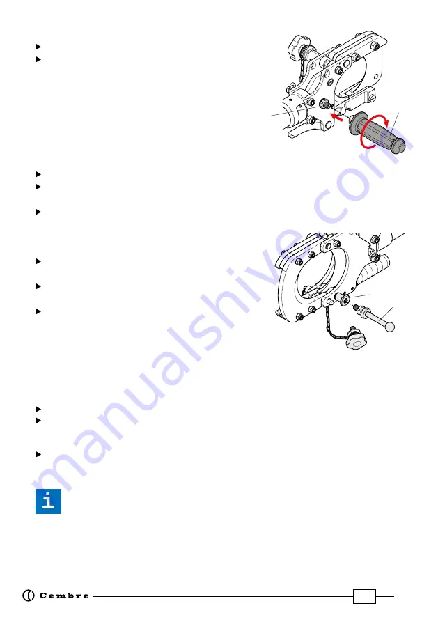
mount the support handle (3) on the head
by screwing it onto the threaded pin (14); when finished using
the unit, remove the handle before storing the head in its case.
4.2) Grounding the cutting head
To ground the cutting head, proceed as follows:
Using a grounding wire with lug termination
Unscrew knob (6) from the grounding socket (16) of the head (Ref. to Fig. 8).
Connect the terminal of the grounding wire to the socket using the knob (6),
fasten the knob
tightly
.
Fully unwind the grounding wire and connect the other end to the grounding system using
the clamp.
Using a grounding wire with ball & socket termination
Unscrew knob (6) from the grounding socket (16) of
the head.
Screw the grounding pin (15) tightly into the
socket (1/2”-13 UNC thread).
Fully unwind the grounding wire and connect one
end to the grounding pin (15) using the clamps and
the other end to the grounding system.
4.3) Positioning the cutting head around the cable
The appropriate cutting head should be chosen based on the size of the cable to be cut.
The cutting head must then be manually positioned around the cable.
TC096Y-KV-RC2:
insert the cable between the blades.
TC085Y-KV-RC2:
release latch (4) to open the blades.
insert the cable, close the head and fully secure the latch (4) (Ref. to Fig. 9).
Ensure that the head is fully secured: partial closure may damage the head.
TC120Y-KV-RC2:
extract the locking pin (8) to open the blades.
Insert the cable, close the head and fully secure the locking pin (8) (Ref. to Fig. 10).
Ensure that the head is fully secured: partial closure may damage the head.
Make sure the blades are positioned exactly on the desired cutting point.
Once the blades of the cutting head are around the cable to be cut, stabilize the head to prevent
any movement during the cutting operation; when used within manholes we recommend the
usage of
SS-TCY support strap
(Ref. to
section 4.4
) in orderto support the head in a stable position.
15
16
14
3
Содержание B68M-P18A-KV-RC2
Страница 2: ...2 FIG 2 A G F C B FIG 1 1 5 9 10 12 8 7 3 2 4 2 11 D 6 E ...
Страница 31: ...31 ...


