


7
ENG
The installation must conform to the require-
ments of the Authority having jurisdiction or,
in the absence of such requirement, to the
National Fuel Gas Code, ANSI Z223.1/NFPA 54
and, or CAN/CGAB149 Installation Code. Where
required by the Authority having jurisdiction, the
installation must conform to the Standard for
Controls and Safety Devices for Automatically
Fired Boilers, ANSI/ASME CSD-1. All boilers
must be installed with a proper pressure relief
valve. Pressure relief valves must be installed
to confirm to ANSI/ASME Boiler and Pressure
Vessel Code, Section IV, or CSA B51, as applicable.
If the boiler is installed above the radiation level,
or as required by the Authority having jurisdiction,
the installer must provide a low water cut-off
device at a time of installation. The boiler must be
installed in a fixed location and only by a qualified
installer, service agency or the gas supplier and is
familiar with the requirement that are contained
in this manual. Furthermore, the installation
must be in accordance with current standars
and regulations. The boiler must not be installed
on carpeting. The boiler when used in connection
with a refrigeration system, must be installed so
the chilled medium is piped in parallel with the boi-
ler with appropriate valves to prevent the chilled
medium from entering the boiler. The boiler piping
system of a hot water boiler connected to heating
coils located in air handling units where they may
be exposed to refrigerated air circulation must
be equipped with flow control valves or other
automatic means to prevent gravity circulation of
the boiler water during the cooling cycle. Service
instructions and recommended frequency gui-
delines periodic examination of venting systems
every six months. Venting systems, the vent-air
intake system, screens in the vent terminal
should be checked and cleaned every six months.
Low water cutoff should be checked and cleaned
every six months. Remove small cover retaining
screw and remove the cover. When the pump
is running and water is flowing around the boiler
, the actuator lifts off the micro switch. Check
that the operation of the actuator ; Ensure that
it is free and that it lifts and returns. If necessary
lubricate the pivot point of the actuator. Flue gas
passageways should be checked and cleaned
every six months. The burner should be checked
and cleaned every six months. Inspect the burner
and if necessary clean using a soft brush and a
vacuum cleaner, taking care not to damage the
front insulation. Check the ignition /ionisation
electrode, check the ignition spark gap (3.5 mm
+/- 0.5 mm) (0.138 in. +/- 0.02 in.). Before reas-
sembly inspect all seals and replace as required.
Furthermore, the installation must be in accor-
dance with current standards and regulations.
2.1
VENTILATION OF BOILER ROOM
When using air from the boiler room, an ade-
quate air supply shall by provided for combu-
stion of this boiler. An insufficient supply can
result in poor combustion and possible sooting
of the burner, combustion chamber or flue
passageway.
The boilers installed using inside air
supply must provide provisions for Combustion
Air and Ventilation Air in accordance with section
53, Air for Combustion and Ventilation, of the
National Flue Gas Code, ANSI Z 223,1/NFPA
54, or section 7,2, 7.3, or 7.4, of CAN/CGA B
149, Installation Codes, or local codes having
jurisdiction. Where an exhaust fan or any other
air consuming appliance is installed in the same
space as the boiler, sufficient air openings must
be available to provide fresh air when all appliance
are operating simultaneously. It is essential that
in rooms where the boiler are installed at least
as much air can arrive as required by normal
combustion of the gas consumed by the various
appliances. Consequently, it is necessary to make
openings in the walls for the air inlet into the
rooms. These openings must meet the following
requirements:
1. Have a total free section of a least 2225
mm
2
every kW (1 in
2
for every 1000 Btu/
hr) of heat input, with a minimum of 100
cm
2
(15.5 in
2
);
2. They must by located not more than 18 in
or less than 6 in above the floor level, not
prone to obstruction and protected by a
grid which does not reduce the effective
section required for the passage of air;
3. Where requide by jursdiction or when
required for additional opening must be
provided at the highest elevation practical.
With a hermetically sealed combustion chamber
and air supply circuit from outdoors, may be
installed in any room in the home. Keep boiler
area clear and free from combustible materials,
gasoline and other flammable vapors and liquids.
2.2 INSTALLATION
PLATE
The installation plate code 6246958 is supplied
with the boiler.
The optional installation plate code 8075416
is supplied with an instruction sheet for the
fixing.
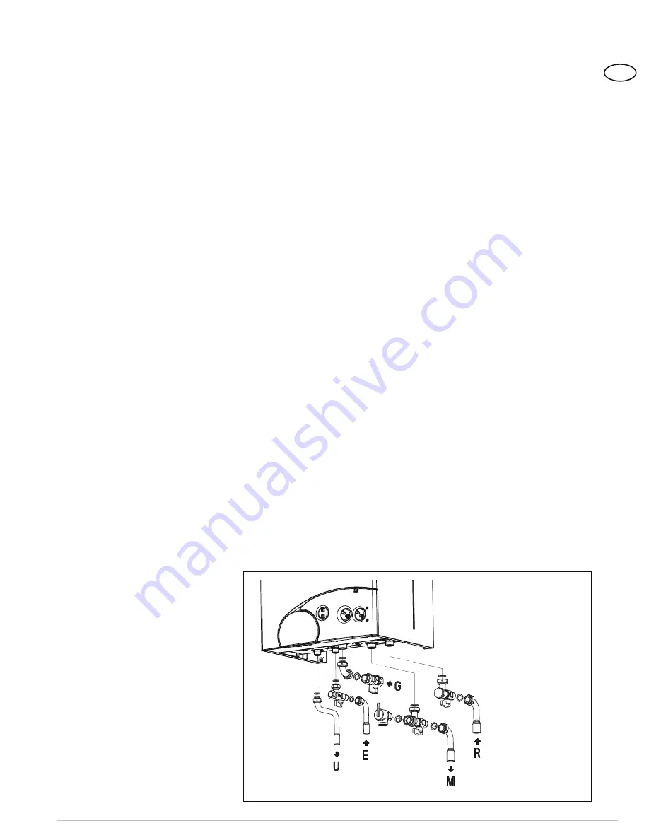
2.2.1 Isolating
valves
kit
To fit the isolating valves, supplied with the boiler,
use figure 4 for assembly.
2.2.2 System
connection
unions
The follow is available to facilitate water and gas
connection of the boiler with the heating system:
for assembly of the unions to see fig. 1.
2.3 CONNECTING
UP
SYSTEM
To protect the heat system from damaging cor-
rosion, flakes or deposits, before installation it is
extremely important to clean the system using
suitable products such as, descaler or slug re-
moving solution. For long-term protection against
corrosion and deposits, the use of inhibitors is re-
quired for new installations and after cleaning the
system. It is important to check the concentration
of the inhibitor after each system modification and
during maintenance following the manufacturer’s
instructions (specific tests are available at your
dealer). The safety valve drain must be connected
to a collection funnel to collect any discharge du-
ring interventions.
If the heating system is on a
higher floor than the boiler, install the on/off taps
supplied in kit on the heating system delivery/re-
turn pipes.
WARNING: Failure to clean the heat system or
add an adequate inhibitor invalidates the devi-
ce’s warranty.
2.3.1 Gas
Requirements
Read the date plate to be sure the water he-
ater is made for the type of gas being used.
An adhesive data plate is stuck inside the front
panel, it contains all the technical data iden-
tifying the boiler and the type of gas for which
the boiler is arranged. If the information does
not agree with the type of gas available, do not
install or operate the water heater. Call your
dealer. The gas piping must be installed accor-
ding to all local and state codes, or in absence
of local and state codes, with the latest “Natu-
ral gas and propane installation code”, CAN/
CSA-B 149.1 or “National Flue Gas Code”,
ANSI Z223.1 (NFPA 54). Consult the “Natural
gas and propane installation code” or “Natio-
nal Flue Gas Code” for the recommended gas
2 INSTALLATION
Figure 4
R C.H.
return
M C.H.
supply
G Gas connection
E D.H.W. inlet
U D.H.W.
outlet
Содержание 35 BF
Страница 29: ...29 ENG 5 EXPLODED VIEWS VUES CLAT ES...
Страница 34: ...34 ENG...
Страница 35: ...35 ENG...
Страница 36: ...315 Oser Avenue Hauppauge NY 11788 Tel 631 694 1800 Fax 631 694 1832 www embassyind com...