________
14
________
SP
D
F
MISE EN SERVICE
INBETRIEBNAHME
PUESTA EN
MARCHA
1 –
Placer l’interrupteur de la chaudière en
position « arrêt » afin d’éviter le
démarrage de celle-ci en phase de
remplissage et de purge.
2
– Remplir le ballon
Ouvrir le robinet eau froide de la
chaudière.
Ouvrir un robinet d’eau chaude de
l’installation pour purger l’air et placer le
groupe dans la position « Alimentation ».
Afin d’accélérer le remplissage, vous
pouvez ouvrir le by-pass (fig. B, rep. 11), à
l’aide du bouton moleté (ouverture en
dévissant, fermeture en vissant).
Vérifier que la bride et tous les joints des
canalisations sont bien étanches.
3
– Rincer le ballon
Cette opération permet d’assurer le
nettoyage de l’appareil. Pour ce faire,
laisser s’écouler l’eau, après remplissage,
pendant quelques minutes. Ceci a
l’avantage de purger le circuit.
4
– Purger la pompe en desserrant le
bouchon du lanceur de celle-ci.
Raccordement électrique
Le raccordement électrique du ballon
s’effectue par l’intermédiaire d’un câble 3
conducteurs (phase, neutre et terre) non
fourni.
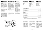
Celui-ci est raccordé sur le bornier selon
figure.
L’interrupteur du ballon sert uniquement à
supprimer la fonction eau chaude sanitaire
sans arrêter la fonction chauffage.
NOTA
:
Il n’y a aucun raccordement
électrique entre la chaudière et le ballon.
1 –
Den kesselschalter auf « stop » stellen
um ein Funktionieren des Kessels
während der Füllphase oder des
Ablassens zu verhindern.
2
– Boiler füllen
Kaltwasserhahn des Heizkessels öffnen.
Einen Warmwasserhahn der Anlage zur
Entlüftung öffnen und den Satz auf
“Alimentation“ (Einlauf) stellen. Um das
Füllen zu beschleunigen, kann der Bypass
(Abb. B, Ref. 11) anhand des Rändelknopfes
geöffnet werden (beim Öffnen auf-, beim
Schliessen zuschrauben).
Darauf achten, daß der Flansch und alle
Leitungsdichtungen wasserdicht sind.
3
– Den Boiler spülen.
Den Apparat wie folgt reinigen : das
Wasser einige minuten nach dem Füllen
überlaufen lassen. So werden zugleich die
Leitungen gereinigt.
4
– Zum Entlüften der Pumpe den Deckel
der Ansaugvorrichtung lösen.
Elektrischer Anschluß
Der Schalter des Boilers dient lediglich
zum Abschalten der Funktion warmes
Leitungswasser ; die Heizung wird nicht
ausgeschaltet.
1
– Colocar el interruptor de la caldera en
posición “paro“, a fin de evitar que la
misma se ponga en marcha cuando esté
en fase de llenado o de purga.
2
– Llenar el acumulador.
Abrir la llave de entrada del agua fría a la
caldera.
Abrir un grifo de agua caliente de la
instalación para purgar el aire y colocar el
grupo en posición « Alimentación ».
Con el fin de acelerar el llenado, se puede
abrir el by-pass (figura B – indicación 11),
con el botón moleteado (destornillar para
abrir, atornillar para cerrar).
Sacar la cubierta protectora y verficar la
estanqueidad de la brida y de lodas las
juntas de las conducciones.
3
– Limpiar el acumulador.
Esta operación permite asegurar la
limpieza del aparato. Para efectuarlo,
dejar vaciar el agua y después rellenarlo,
durante algunos minulos. Esto tiene como
ventaja el purgar el circuito.
4
– Aflojar el tapón de arranque de la
bomba para purgala.
Conexión eléctrica
El interruptor del acumulador sólo sirve
para suprimir la función agua caliente
sanitaria sin detener la función
calefacción.
NOTA :
No hay ninguna conexión
eléctrica entre la caldera y el acumulador.
N
P
Thermostat
Thermostat
Termostato
Bornier
Anschlußklemme
Borne
Terre
Erde
Tierra
Neutre
Neutral
Neutro
220V mono ~ 50Hz
Phase
Phase
Fase
Fusible
Sicherung
Fusible
Interrupteur avec voyant
Schalter mit signallampe
Interruptor con indicator
________
7
________
NL
I
GB
PERFORMANCE
PRESTAZIONI
PRESTATIES
The CELECTIC may be used in
conjunction with the following boilers :
CELTIC FF
STERLING FF
STERLING OF
II CELECTIC funziona con le seguenti
caldaie
MULTI VENTI TOP
MULTI VENTI 4 TOP
CERAR VENTI TOP
CERAR VENTI 4 TOP
MULTI VENTI FF TOP FF
CERAR VENTI FF TOP FF
SIAM CF
MC 13.20
CELTIC 2.26 Rsc b
SIAM FF
MC 13.20 FF
De CELECTIC werkt met de volgende
wandketels :
NEWTECH 2.20 FF
NEWTECH 2.20
NEWTECH 2.24
NEWTECH 2.20 HPS
SIAM CF
SIAM FF
GM 13.20 Rsc b
NEWTECH 2.20 FFHPS
Data given for a 23 kW boiler output*
Tabella data per una caldaia di 23 kW*
Gegeventabel voor een wandketel van 23 kW*
80 l
100 l
150 l
Heat recovery time at 15 to 60° C (min)
Durata di riscaldamento da 15 a 60° C (min)
Opwarmingstijd 15 tot 60° C (min)
25
30
40
Flow rate ltrs/min
Portata specifica l/min
Specifiek debiet l/min
17
17,6
20,9
Stand-by consumption kWh/24 hrs
Consumo di mantenimento kWh/24 h
Onderhoudsverbruik kWu/24 u
1,58
1,63
1,94
Stand-by coefficient watts/sq.mtr/° C
Constante di raffreddamento
Afkoelingsconstante
0,493
0,408
0,323
Type of electrical protection
Classe di protezione elettrica
Elektrische beschermingsgraad
IPX4
IPX4
IPX4
* the figures quoted in the above table refer to a top outlet cylinder connected directly beneath the combination boiler.
* I valori della tabella sono stabiliti per un sebatoio collegato dall’alto e piazzato sulla caldaia.
* De waarden van deze tabel zijn opgemaakt voor een watervermarmer boven aangesloten en geïnstalleerd onder de wandketel.
To maximise system performance and
minimise both pressure and thermal
losses due to extented pipe runs, it is
recommended that the cylinder is installed
as close to the boiler as possible.
However, the Celectic can be installed up
to a maximum of 10 mtrs away from the
boiler provided that frictional losses are
kept to a minimum, through the use of
machined bends rather than elbows and
that all pipework is insulated to reduce
thermal losses.
This flexibility allows the Celectic to be
installed in cupboards, kitchens, cellars,
etc. remote from the boiler, provided that
the installation instructions are adhered to.
Si raccomanda di sistemare il serbatoio il
più vicino possibile alla caldaia al fine di
non far diminuire le prestazioni del
sistema per le perdite di carica e per le
perdite termiche nelle tubature.
Comunque una lunghezza equivalente a
20 m di tuberia 16x28 è possibile (il che
corrisponde a 10 m andata e ritorno)
senza tener conto degli inconvenienti di
percorso che sono da dedure a questa
massima lunghezza.
E necessario isolare termicamente i tubi di
collegamento.
II serbatoio puo essere collocato ovunque
(stipo, cucina, cantina purché siano
rispettate le istruzioni di montaggio).
Het is aanbevolen om de boiler zo dicht
mogelijk bij de ketel te plaaten, teneinde
de prestaties niet te doen dalen, door
drukverliesen en thermische verliezen in
de leidingen.
Niettemin is een equivalente lengte van 20
m buisleiding 16x28 mogelijk (welke
overeenkomt met 10 m vertrek en retour)
zonder rekening te houden met de
verschillende obstakels op het circuit,
welke moeten afgetrokken worden van
deze maximum lengte.
Het is eveneens noodzakelijk om de
aansluitleidingen thermisch te isoleren.
De boiler mag gelijk waar geplaastst worden
(muurkast, keuken, kelder,…) onder
voorbehoud dat de montageinstrukties
gerespekteerd worden.
________
14
________
SP
D
F
MISE EN SERVICE
INBETRIEBNAHME
PUESTA EN
MARCHA
1 –
Placer l’interrupteur de la chaudière en
position « arrêt » afin d’éviter le
démarrage de celle-ci en phase de
remplissage et de purge.
2
– Remplir le ballon
Ouvrir le robinet eau froide de la
chaudière.
Ouvrir un robinet d’eau chaude de
l’installation pour purger l’air et placer le
groupe dans la position « Alimentation ».
Afin d’accélérer le remplissage, vous
pouvez ouvrir le by-pass (fig. B, rep. 11), à
l’aide du bouton moleté (ouverture en
dévissant, fermeture en vissant).
Vérifier que la bride et tous les joints des
canalisations sont bien étanches.
3
– Rincer le ballon
Cette opération permet d’assurer le
nettoyage de l’appareil. Pour ce faire,
laisser s’écouler l’eau, après remplissage,
pendant quelques minutes. Ceci a
l’avantage de purger le circuit.
4
– Purger la pompe en desserrant le
bouchon du lanceur de celle-ci.
Raccordement électrique
Le raccordement électrique du ballon
s’effectue par l’intermédiaire d’un câble 3
conducteurs (phase, neutre et terre) non
fourni.
Celui-ci est raccordé sur le bornier selon
figure.
L’interrupteur du ballon sert uniquement à
supprimer la fonction eau chaude sanitaire
sans arrêter la fonction chauffage.
NOTA
:
Il n’y a aucun raccordement
électrique entre la chaudière et le ballon.
1 –
Den kesselschalter auf « stop » stellen
um ein Funktionieren des Kessels
während der Füllphase oder des
Ablassens zu verhindern.
2
– Boiler füllen
Kaltwasserhahn des Heizkessels öffnen.
Einen Warmwasserhahn der Anlage zur
Entlüftung öffnen und den Satz auf
“Alimentation“ (Einlauf) stellen. Um das
Füllen zu beschleunigen, kann der Bypass
(Abb. B, Ref. 11) anhand des Rändelknopfes
geöffnet werden (beim Öffnen auf-, beim
Schliessen zuschrauben).
Darauf achten, daß der Flansch und alle
Leitungsdichtungen wasserdicht sind.
3
– Den Boiler spülen.
Den Apparat wie folgt reinigen : das
Wasser einige minuten nach dem Füllen
überlaufen lassen. So werden zugleich die
Leitungen gereinigt.
4
– Zum Entlüften der Pumpe den Deckel
der Ansaugvorrichtung lösen.
Elektrischer Anschluß
Der Schalter des Boilers dient lediglich
zum Abschalten der Funktion warmes
Leitungswasser ; die Heizung wird nicht
ausgeschaltet.
1
– Colocar el interruptor de la caldera en
posición “paro“, a fin de evitar que la
misma se ponga en marcha cuando esté
en fase de llenado o de purga.
2
– Llenar el acumulador.
Abrir la llave de entrada del agua fría a la
caldera.
Abrir un grifo de agua caliente de la
instalación para purgar el aire y colocar el
grupo en posición « Alimentación ».
Con el fin de acelerar el llenado, se puede
abrir el by-pass (figura B – indicación 11),
con el botón moleteado (destornillar para
abrir, atornillar para cerrar).
Sacar la cubierta protectora y verficar la
estanqueidad de la brida y de lodas las
juntas de las conducciones.
3
– Limpiar el acumulador.
Esta operación permite asegurar la
limpieza del aparato. Para efectuarlo,
dejar vaciar el agua y después rellenarlo,
durante algunos minulos. Esto tiene como
ventaja el purgar el circuito.
4
– Aflojar el tapón de arranque de la
bomba para purgala.
Conexión eléctrica
El interruptor del acumulador sólo sirve
para suprimir la función agua caliente
sanitaria sin detener la función
calefacción.
NOTA :
No hay ninguna conexión
eléctrica entre la caldera y el acumulador.
N
P
Thermostat
Thermostat
Termostato
Bornier
Anschlußklemme
Borne
Terre
Erde
Tierra
Neutre
Neutral
Neutro
220V mono ~ 50Hz
Phase
Phase
Fase
Fusible
Sicherung
Fusible
Interrupteur avec voyant
Schalter mit signallampe
Interruptor con indicator
________
7
________
NL
I
GB
PERFORMANCE
PRESTAZIONI
PRESTATIES
The CELECTIC may be used in
conjunction with the following boilers :
CELTIC FF
STERLING FF
STERLING OF
II CELECTIC funziona con le seguenti
caldaie
MULTI VENTI TOP
MULTI VENTI 4 TOP
CERAR VENTI TOP
CERAR VENTI 4 TOP
MULTI VENTI FF TOP FF
CERAR VENTI FF TOP FF
SIAM CF
MC 13.20
CELTIC 2.26 Rsc b
SIAM FF
MC 13.20 FF
De CELECTIC werkt met de volgende
wandketels :
NEWTECH 2.20 FF
NEWTECH 2.20
NEWTECH 2.24
NEWTECH 2.20 HPS
SIAM CF
SIAM FF
GM 13.20 Rsc b
NEWTECH 2.20 FFHPS
Data given for a 23 kW boiler output*
Tabella data per una caldaia di 23 kW*
Gegeventabel voor een wandketel van 23 kW*
80 l
100 l
150 l
Heat recovery time at 15 to 60° C (min)
Durata di riscaldamento da 15 a 60° C (min)
Opwarmingstijd 15 tot 60° C (min)
25
30
40
Flow rate ltrs/min
Portata specifica l/min
Specifiek debiet l/min
17
17,6
20,9
Stand-by consumption kWh/24 hrs
Consumo di mantenimento kWh/24 h
Onderhoudsverbruik kWu/24 u
1,58
1,63
1,94
Stand-by coefficient watts/sq.mtr/° C
Constante di raffreddamento
Afkoelingsconstante
0,493
0,408
0,323
Type of electrical protection
Classe di protezione elettrica
Elektrische beschermingsgraad
IPX4
IPX4
IPX4
* the figures quoted in the above table refer to a top outlet cylinder connected directly beneath the combination boiler.
* I valori della tabella sono stabiliti per un sebatoio collegato dall’alto e piazzato sulla caldaia.
* De waarden van deze tabel zijn opgemaakt voor een watervermarmer boven aangesloten en geïnstalleerd onder de wandketel.
To maximise system performance and
minimise both pressure and thermal
losses due to extented pipe runs, it is
recommended that the cylinder is installed
as close to the boiler as possible.
However, the Celectic can be installed up
to a maximum of 10 mtrs away from the
boiler provided that frictional losses are
kept to a minimum, through the use of
machined bends rather than elbows and
that all pipework is insulated to reduce
thermal losses.
This flexibility allows the Celectic to be
installed in cupboards, kitchens, cellars,
etc. remote from the boiler, provided that
the installation instructions are adhered to.
Si raccomanda di sistemare il serbatoio il
più vicino possibile alla caldaia al fine di
non far diminuire le prestazioni del
sistema per le perdite di carica e per le
perdite termiche nelle tubature.
Comunque una lunghezza equivalente a
20 m di tuberia 16x28 è possibile (il che
corrisponde a 10 m andata e ritorno)
senza tener conto degli inconvenienti di
percorso che sono da dedure a questa
massima lunghezza.
E necessario isolare termicamente i tubi di
collegamento.
II serbatoio puo essere collocato ovunque
(stipo, cucina, cantina purché siano
rispettate le istruzioni di montaggio).
Het is aanbevolen om de boiler zo dicht
mogelijk bij de ketel te plaaten, teneinde
de prestaties niet te doen dalen, door
drukverliesen en thermische verliezen in
de leidingen.
Niettemin is een equivalente lengte van 20
m buisleiding 16x28 mogelijk (welke
overeenkomt met 10 m vertrek en retour)
zonder rekening te houden met de
verschillende obstakels op het circuit,
welke moeten afgetrokken worden van
deze maximum lengte.
Het is eveneens noodzakelijk om de
aansluitleidingen thermisch te isoleren.
De boiler mag gelijk waar geplaastst worden
(muurkast, keuken, kelder,…) onder
voorbehoud dat de montageinstrukties
gerespekteerd worden.


