________
4
________
SP
D
F
PRESENTATION
ALLGEMEINES
BESCHREIBUNG
PRESENTACION
B
Le ballon « CELECTIC » est un système
de production d’eau chaude accumulée à
partir des chaudières mixtes Chaffoteaux
et Maury.
Le ballon est équipé d’une pompe, d’un
boîtier électrique de raccordement, d’un
groupe de sécurité et d’un capot de
protection.
La cuve à fonds positifs est en acier
émaillé de forte épaisseur. Elle est
équipée d’une anode en magnésium
agissant comme protection électrolytique.
Le calorifugeage est assuré par une
couche de mousse polyuréthane.
Le ballon est raccordé à la partie sanitaire
chaudière par les sorties (2) et (3), à
l’installation ECS par la sortie (1) et à
l’arrivée d’eau froide par l’entrée (4).
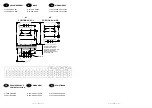
C Principe de
fonctionnement
(1) Départ ECS vers puisage
(2) Départ vers chaudière
(3) Retour ECS chaudière
(4) Arrivée eau froide
(5) Pompe
(6) Groupe de sécurité
(7) Thermostat
(8) Boîtier de raccordement électrique
(9) Capot de protection
(10) Pattes d’accrochage
(12) Interrupteur
(13) Anode
1 - Statique
:
L’eau du ballon est réchauffée automati-
quement par la chaudière sur ordre du
thermostat (7) qui déclenche le fonction-
nement de la pompe (5).
Celle-ci a pour rôle de faire circuler l’eau
du ballon dans la chaudière et provoquer
le réchauffage de celle-ci à la température
de réglage du thermostat.
2 – Dynamique
:
En puisage, l’eau froide arrivant par (4)
passe automatiquement par la chaudière,
ce qui entraîne son entrée en température
dans le ballon.
B
Der druchlauferhitzer CELECTIC bereitet
und speichert Warmwasser ab Mischkessel
Chaffoteaux et Maury.
Der boiler ist mit einer Pumpe, einem
Anschlußschaltkasten, einer Sicherheits-
vorrichtung und einer Schutzverkleidung
versehen.
Der Behälter hat einen Plusboden aus
sehr dickem emailliertem Stahl. Er besitzt
eine Anode aus Magnesium, die wie ein
elektrolytischer schutz wirkt.
Eine Schicht aus Polyurethanschaum
sorgt für die Wärmeisolierung.
Der Boiler wird an die sanitären teile des
Kessels angeschlossen über die
ausflußpunkte (2) und (3), an die Warm-
wasserinstallation über (1) und an die
Kaltwasserzufuhr über (4).
C Shematische
Darstellung
(1) Abfluß Warmwasser zum Abzapfpunkt
(2) Abfluß zum kessel
(3) Warmwasser Rückflauf
(4) Kaltwasserzufuhr
(5) Pumpe
(6) Sicherheitsanlage
(7) Thermostat
(8) Anschlußschaltkasten
(9) Schutzgehaüse
(10) Halterungen
(12) Schalter
(13) Anode
1 – Feste Teile
:
Das Wasser im Boiler wird automatisch
durch den Kessel erhitzt, auf Befehl des
Thermostats (7) der die Pumpe (5)
auslöst. Die Pumpe erlaubt dem Wasser
im Boiler durch den Kessel zu fließen.
Dort wird es je nach Einstellung des
Thermostats erhitzt.
2 – Bewegliche Teile
:
Bei der Warsserentnahme fließt das von
(4) kommende Kaltwasser automatisch
durch den Kessel, und löst die Erhitzung
im Kessel aus.
B
El acumulador “CELECTIC“ es un sistema
de producción de agua caliente acumulada
acoplable a las calderas mixtas Chaffoteaux
et Maury.
El acumulador viene equipado con una
bomba, una caja eléctrica de conexión, un
grupo de seguridad y una tapa de
protección.
La cuba de fondos convexos es de acero
esmaltado de gran espesor. Está
equipada por un ánodo de magnesio que
actúa como protección electrolítica.
La calorirugación queda asegurada
mediante una capa de espuma de
poliuretano.
C Esquema de principio
Principio de funciona-
miento
(1) Salida ACS hacia el punto de
extaccion
(2) Salida hacia la caldera
(3) Retorno ACS de la caldera
(4) Llegada de agua fría
(5) Bomba
(6) Grupo de seguridad
(7) Termostatos
(8) Caja de conexión eléctrica
(9) Tapa protectora
(10) Patas de sujeción
(12) Interruptor
(13) Anodo
Principio de funcionamiento
El acumulador está empalmado a la parte
sanitaria de la caldera por las salidas (2) y
(3), a la instalación ACS por la solida (1) y
a la llegada de agua fría por la entrada (4).
1 – Estatica :
El agua del acumulador se recalienta
automáticamente por la caldera según la
órden del termostato (7), el cuál acciona
el funcionamento de la bomba (5).
Esta tiene como función, hacer circular el
agua del acumulador en el interior de la
caldera y provocar el recalentamiento de
ésta según la temperatura indicada en el
termostato.
2 – Dinamica :
A la extracción, el agua fría que llega por
(4) pasa automáticamente por la cladera,
con lo cual entra al acumulador una vez
calentada.
________
17
________
NL
I
GB
Adjustments
The cylinder thermostat is set to obtain a
nominal domestic hot water temperature
of 65° C.
It is therefore important that the
temperature control for the domestic hot
water, on the boiler, is set to maximum to
ensure that the delivery of hot water
exceeds the mean temperature of the
cylinder.
Installing the cover
Once the installation has been completed
and tested, the protective cover can now
be fitted. This is done by placing it under
the bracket (or brackets in the case of the
150 ltrs) at the rear of the cylinder and
sliding it into position. Secure by
tightening the two fixing screws onto the
cylinder.
Maintenance schedule
To maintain the correct and safe operation
of the Celectic unit, it is essential that the
safety valve assembly is operated
manually at least once a month, by
depressing the lever and checking that
water discharges from the valve.
If the valve fails to discharge water, then
the Celectic unit must be turned off by
isolating both the electrical and water
supplies.
Contact your service company or agent.
Anode
It is necessary to change the anode every
two years.
To turn off the Celectic system
IMPORTANT : If the unlikely event of the
boiler failing, the Celectic should be turned
off by isolating the electrical supply via the
on/off switch.
If this is not implemented the integral
pump will continue to function and
circulate the stored water through the
secondary heat exchanger in the boiler,
thus resulting in stand-by losses.
Heating only
This can be achieved by simply setting the
summer and winter switch on the boiler to
the winter position (hot water and heating)
and the Celectic switch to the stop
position.
Heating and hot water
As heating only, except turn the Celectic
isolating switch to the on position.
NOTA
: Priority will always be given to the
heating the domestic hot water cylinder.
Central heating will only operate once the
cylinder temperature has reached its set
level.
Regulazione
Il termostato del serbatoio è regolato in
modo da ottenere dell’acqua calda
sanitaria a circa 65° C.
Cosi, conformemente all’istruzione ECS
(acqua calda sanitaria) di 60° C, portata
su alcune caldaie, é necessario regolare
la temperatura dell’acqua calda sanitaria
al massimo in tal modo che essa sia
superiore al punto di consegna del
termostato dello scaldabagno.
Montaggio della cuffia di protezione
Una volta montato l’assieme, piazzare la
cuffia di protezione facendolo scivolare
sotto le due staffe dietro il serbatoio e
fissarla con le due viti sulla ghiera del
serbatoio.
Manutenzione
–
utilizzazione
Cruppo di sicurezza
Al fine di assicurare il buon funzionamento
del gruppo di sicurezza è necessario farlo
funzionare almeno una volta al mese
azionando la leva e verificando che
l’acqua scorra normalmente.
Se l’acqua non scorre, è il caso di far
intervenire urgentemente uno specialista,
dopo aver spento l’apparecchio.
Anodo
E obligatorio il cambiamento di anodo tutti
i due ani.
Arresto dell’impianto
IMPORTANT : In caso di arresto della
caldaia, è necessario interrompere
l’alimentazione elettrica del serbatoio. In
caso contrario, la pompa farà inutilmente
circolare l’acqua fredda nella caldaia in
modo permanente
Riscaldamento senza acqua calda
sanitaria
Se si desidera avere il riscaldamento
dell’impiando sonza riscaldare il serbatoio,
basta accendere la caldaia lasciando
l’interruttore del serbatoio in posizione
spenta.
Riscaldamento ed acqua calda
sanitaria
Al fine di ottenere l’acqua calda sanitaria,
una volta messa in funzione la caldaia,
basta ma novrare l’interrutore del
serbatoio, il che provoca il riscaldamento
dell’acqua in esso contenuta.
NOTA
: Data la priorità all’impianto
sanitario della caldaia, essa non proddurà il
riscaldamento dell’impianto fino a quando
l’acqua contenuta nel serbatoio non ha
raggiunto la temperatura fissata con il
termostato. In caso di non utilizzazione
dell’impianto in periodo freddo, è
necessario svuotare il serbatoio per
prevenire il gelo. Chiudere l’arrivo d’acqua
del gruppo di sicurezza. Aprire un rubinetto
d’acqua calda. Smontare il collegamento
(Rep. B) al serbatoio. Piazzare un raccordo
del tipo tubo d’innaffiamento con un tubo di
gomma. Svuotare il serbatoio mediante
travasamento. Rimontare il collegamento.
Regelingen
De aquastaat van de boiler is ingesteld
om sanitair warm water te bekomen van
ongeveer 65°C.
Op de wandketels, uitgerust met een
regeling van de temperatuur van het
SWW op 60°C, is het noodzakelijk om de
temperatuur van het sanitair warm water
te regelen op het maximum, zodat deze
hoger is dan het consigne-punt van de
thermostaat van de boiler.
Plaatsing van de beschermkap
Eens het geheel gemonteerd, de bes-
chermkap plaatsen door deze onder de 2
haken aan de achterkant van de boiler te
schuiven en deze vast te maken door de 2
vijzen op de flens van de boiler.
Onderhoud – gebruik
Veiligheidsgroep
Teneinde een goede werking van de
veiligheidsgroep te verzekeren, is het
noodzakelijk om deze minimum 1 maal
per maand te spuien door de handel te
bewegen en na te kijken of het water
normaal wegloopt.
Indien het water niet afloopt, is het
noodzakelijk om dringend een vakman te
laten komen, na het toestel afgesloten te
hebben.
Anode
Het is verplicht de anode om de twee jaar
te vervangen.
Stilstand van de installatie
BELANGRIJK : in geval van stilstand van
de ketel, is het noodzakelijk op de
elektrische voeding van de boiler te
verbreken. Indien dit niet gebeurt, zal de
pomp het koud water in de boiler onnodig
doen cirkuleren.
Verwarming zonder sanitair warm
water
Indien men verwarming wenst zonder
opwarming van de boiler, volstaat het de
ketel in werking te stellen en de
schakelaar van de boiler op stand “stop”
te laten.
Verwarming met/of sanitair warm water
Teneinde sanitair warm water te
bekomen, eens de ketel in werking,
volstaat het om de schakelaar in te stellen
om de inhoud van de boiler op te warmen.
NOTA
: Gezien de voorrang van het
sanitair van de ketel, zal deze de
verwarming stoppen tot het water in de
boiler opgewarmd is.
Indien de installatie niet wordt gebruikt
gedurende een gerude de winterpériode,
is het noodzakelijk de waterverwarmer te
ledigen om bevriezing te voorkomen
aankomst water aan de veiligheidsgroep
sluiten.
Een warmwaterkraan openen. De
aansluiting aan de boiler demonteren (rep
B). Een annsluitstuk plaatsen van het type
sproeislang met een buis incaoutchoucc.
________
4
________
SP
D
F
PRESENTATION
ALLGEMEINES
BESCHREIBUNG
PRESENTACION
B
Le ballon « CELECTIC » est un système
de production d’eau chaude accumulée à
partir des chaudières mixtes Chaffoteaux
et Maury.
Le ballon est équipé d’une pompe, d’un
boîtier électrique de raccordement, d’un
groupe de sécurité et d’un capot de
protection.
La cuve à fonds positifs est en acier
émaillé de forte épaisseur. Elle est
équipée d’une anode en magnésium
agissant comme protection électrolytique.
Le calorifugeage est assuré par une
couche de mousse polyuréthane.
Le ballon est raccordé à la partie sanitaire
chaudière par les sorties (2) et (3), à
l’installation ECS par la sortie (1) et à
l’arrivée d’eau froide par l’entrée (4).
C Principe de
fonctionnement
(1) Départ ECS vers puisage
(2) Départ vers chaudière
(3) Retour ECS chaudière
(4) Arrivée eau froide
(5) Pompe
(6) Groupe de sécurité
(7) Thermostat
(8) Boîtier de raccordement électrique
(9) Capot de protection
(10) Pattes d’accrochage
(12) Interrupteur
(13) Anode
1 - Statique
:
L’eau du ballon est réchauffée automati-
quement par la chaudière sur ordre du
thermostat (7) qui déclenche le fonction-
nement de la pompe (5).
Celle-ci a pour rôle de faire circuler l’eau
du ballon dans la chaudière et provoquer
le réchauffage de celle-ci à la température
de réglage du thermostat.
2 – Dynamique
:
En puisage, l’eau froide arrivant par (4)
passe automatiquement par la chaudière,
ce qui entraîne son entrée en température
dans le ballon.
B
Der druchlauferhitzer CELECTIC bereitet
und speichert Warmwasser ab Mischkessel
Chaffoteaux et Maury.
Der boiler ist mit einer Pumpe, einem
Anschlußschaltkasten, einer Sicherheits-
vorrichtung und einer Schutzverkleidung
versehen.
Der Behälter hat einen Plusboden aus
sehr dickem emailliertem Stahl. Er besitzt
eine Anode aus Magnesium, die wie ein
elektrolytischer schutz wirkt.
Eine Schicht aus Polyurethanschaum
sorgt für die Wärmeisolierung.
Der Boiler wird an die sanitären teile des
Kessels angeschlossen über die
ausflußpunkte (2) und (3), an die Warm-
wasserinstallation über (1) und an die
Kaltwasserzufuhr über (4).
C Shematische
Darstellung
(1) Abfluß Warmwasser zum Abzapfpunkt
(2) Abfluß zum kessel
(3) Warmwasser Rückflauf
(4) Kaltwasserzufuhr
(5) Pumpe
(6) Sicherheitsanlage
(7) Thermostat
(8) Anschlußschaltkasten
(9) Schutzgehaüse
(10) Halterungen
(12) Schalter
(13) Anode
1 – Feste Teile
:
Das Wasser im Boiler wird automatisch
durch den Kessel erhitzt, auf Befehl des
Thermostats (7) der die Pumpe (5)
auslöst. Die Pumpe erlaubt dem Wasser
im Boiler durch den Kessel zu fließen.
Dort wird es je nach Einstellung des
Thermostats erhitzt.
2 – Bewegliche Teile
:
Bei der Warsserentnahme fließt das von
(4) kommende Kaltwasser automatisch
durch den Kessel, und löst die Erhitzung
im Kessel aus.
B
El acumulador “CELECTIC“ es un sistema
de producción de agua caliente acumulada
acoplable a las calderas mixtas Chaffoteaux
et Maury.
El acumulador viene equipado con una
bomba, una caja eléctrica de conexión, un
grupo de seguridad y una tapa de
protección.
La cuba de fondos convexos es de acero
esmaltado de gran espesor. Está
equipada por un ánodo de magnesio que
actúa como protección electrolítica.
La calorirugación queda asegurada
mediante una capa de espuma de
poliuretano.
C Esquema de principio
Principio de funciona-
miento
(1) Salida ACS hacia el punto de
extaccion
(2) Salida hacia la caldera
(3) Retorno ACS de la caldera
(4) Llegada de agua fría
(5) Bomba
(6) Grupo de seguridad
(7) Termostatos
(8) Caja de conexión eléctrica
(9) Tapa protectora
(10) Patas de sujeción
(12) Interruptor
(13) Anodo
Principio de funcionamiento
El acumulador está empalmado a la parte
sanitaria de la caldera por las salidas (2) y
(3), a la instalación ACS por la solida (1) y
a la llegada de agua fría por la entrada (4).
1 – Estatica :
El agua del acumulador se recalienta
automáticamente por la caldera según la
órden del termostato (7), el cuál acciona
el funcionamento de la bomba (5).
Esta tiene como función, hacer circular el
agua del acumulador en el interior de la
caldera y provocar el recalentamiento de
ésta según la temperatura indicada en el
termostato.
2 – Dinamica :
A la extracción, el agua fría que llega por
(4) pasa automáticamente por la cladera,
con lo cual entra al acumulador una vez
calentada.
________
17
________
NL
I
GB
Adjustments
The cylinder thermostat is set to obtain a
nominal domestic hot water temperature
of 65° C.
It is therefore important that the
temperature control for the domestic hot
water, on the boiler, is set to maximum to
ensure that the delivery of hot water
exceeds the mean temperature of the
cylinder.
Installing the cover
Once the installation has been completed
and tested, the protective cover can now
be fitted. This is done by placing it under
the bracket (or brackets in the case of the
150 ltrs) at the rear of the cylinder and
sliding it into position. Secure by
tightening the two fixing screws onto the
cylinder.
Maintenance schedule
To maintain the correct and safe operation
of the Celectic unit, it is essential that the
safety valve assembly is operated
manually at least once a month, by
depressing the lever and checking that
water discharges from the valve.
If the valve fails to discharge water, then
the Celectic unit must be turned off by
isolating both the electrical and water
supplies.
Contact your service company or agent.
Anode
It is necessary to change the anode every
two years.
To turn off the Celectic system
IMPORTANT : If the unlikely event of the
boiler failing, the Celectic should be turned
off by isolating the electrical supply via the
on/off switch.
If this is not implemented the integral
pump will continue to function and
circulate the stored water through the
secondary heat exchanger in the boiler,
thus resulting in stand-by losses.
Heating only
This can be achieved by simply setting the
summer and winter switch on the boiler to
the winter position (hot water and heating)
and the Celectic switch to the stop
position.
Heating and hot water
As heating only, except turn the Celectic
isolating switch to the on position.
NOTA
: Priority will always be given to the
heating the domestic hot water cylinder.
Central heating will only operate once the
cylinder temperature has reached its set
level.
Regulazione
Il termostato del serbatoio è regolato in
modo da ottenere dell’acqua calda
sanitaria a circa 65° C.
Cosi, conformemente all’istruzione ECS
(acqua calda sanitaria) di 60° C, portata
su alcune caldaie, é necessario regolare
la temperatura dell’acqua calda sanitaria
al massimo in tal modo che essa sia
superiore al punto di consegna del
termostato dello scaldabagno.
Montaggio della cuffia di protezione
Una volta montato l’assieme, piazzare la
cuffia di protezione facendolo scivolare
sotto le due staffe dietro il serbatoio e
fissarla con le due viti sulla ghiera del
serbatoio.
Manutenzione
–
utilizzazione
Cruppo di sicurezza
Al fine di assicurare il buon funzionamento
del gruppo di sicurezza è necessario farlo
funzionare almeno una volta al mese
azionando la leva e verificando che
l’acqua scorra normalmente.
Se l’acqua non scorre, è il caso di far
intervenire urgentemente uno specialista,
dopo aver spento l’apparecchio.
Anodo
E obligatorio il cambiamento di anodo tutti
i due ani.
Arresto dell’impianto
IMPORTANT : In caso di arresto della
caldaia, è necessario interrompere
l’alimentazione elettrica del serbatoio. In
caso contrario, la pompa farà inutilmente
circolare l’acqua fredda nella caldaia in
modo permanente
Riscaldamento senza acqua calda
sanitaria
Se si desidera avere il riscaldamento
dell’impiando sonza riscaldare il serbatoio,
basta accendere la caldaia lasciando
l’interruttore del serbatoio in posizione
spenta.
Riscaldamento ed acqua calda
sanitaria
Al fine di ottenere l’acqua calda sanitaria,
una volta messa in funzione la caldaia,
basta ma novrare l’interrutore del
serbatoio, il che provoca il riscaldamento
dell’acqua in esso contenuta.
NOTA
: Data la priorità all’impianto
sanitario della caldaia, essa non proddurà il
riscaldamento dell’impianto fino a quando
l’acqua contenuta nel serbatoio non ha
raggiunto la temperatura fissata con il
termostato. In caso di non utilizzazione
dell’impianto in periodo freddo, è
necessario svuotare il serbatoio per
prevenire il gelo. Chiudere l’arrivo d’acqua
del gruppo di sicurezza. Aprire un rubinetto
d’acqua calda. Smontare il collegamento
(Rep. B) al serbatoio. Piazzare un raccordo
del tipo tubo d’innaffiamento con un tubo di
gomma. Svuotare il serbatoio mediante
travasamento. Rimontare il collegamento.
Regelingen
De aquastaat van de boiler is ingesteld
om sanitair warm water te bekomen van
ongeveer 65°C.
Op de wandketels, uitgerust met een
regeling van de temperatuur van het
SWW op 60°C, is het noodzakelijk om de
temperatuur van het sanitair warm water
te regelen op het maximum, zodat deze
hoger is dan het consigne-punt van de
thermostaat van de boiler.
Plaatsing van de beschermkap
Eens het geheel gemonteerd, de bes-
chermkap plaatsen door deze onder de 2
haken aan de achterkant van de boiler te
schuiven en deze vast te maken door de 2
vijzen op de flens van de boiler.
Onderhoud – gebruik
Veiligheidsgroep
Teneinde een goede werking van de
veiligheidsgroep te verzekeren, is het
noodzakelijk om deze minimum 1 maal
per maand te spuien door de handel te
bewegen en na te kijken of het water
normaal wegloopt.
Indien het water niet afloopt, is het
noodzakelijk om dringend een vakman te
laten komen, na het toestel afgesloten te
hebben.
Anode
Het is verplicht de anode om de twee jaar
te vervangen.
Stilstand van de installatie
BELANGRIJK : in geval van stilstand van
de ketel, is het noodzakelijk op de
elektrische voeding van de boiler te
verbreken. Indien dit niet gebeurt, zal de
pomp het koud water in de boiler onnodig
doen cirkuleren.
Verwarming zonder sanitair warm
water
Indien men verwarming wenst zonder
opwarming van de boiler, volstaat het de
ketel in werking te stellen en de
schakelaar van de boiler op stand “stop”
te laten.
Verwarming met/of sanitair warm water
Teneinde sanitair warm water te
bekomen, eens de ketel in werking,
volstaat het om de schakelaar in te stellen
om de inhoud van de boiler op te warmen.
NOTA
: Gezien de voorrang van het
sanitair van de ketel, zal deze de
verwarming stoppen tot het water in de
boiler opgewarmd is.
Indien de installatie niet wordt gebruikt
gedurende een gerude de winterpériode,
is het noodzakelijk de waterverwarmer te
ledigen om bevriezing te voorkomen
aankomst water aan de veiligheidsgroep
sluiten.
Een warmwaterkraan openen. De
aansluiting aan de boiler demonteren (rep
B). Een annsluitstuk plaatsen van het type
sproeislang met een buis incaoutchoucc.


