________
16
________
SP
D
F
Réglages
L’aquatast du ballon est réglé de façon à
obtenir de l’eau chaude sanitaire à 65° C
environ.
Ainsi, sur les chaudières équipées d’une
consigne ECS de 60° C, il est nécessaire
de régler la température de l’eau chaude
sanitaire au maximum, de façon à ce
qu’elle soit supérieure au point de
consigne du thermostat du ballon.
Montage du capot
Une fois l’ensemble monté, placer le capot
de protection en le glissant sous les deux
pattes à l’arrière du ballon et le fixer par
les deux vis sur la virole du ballon.
Entretien – utilisation
Groupe de sécurité
Afin de s’assurer du bon fonctionnement
du groupe de sécurité, il est nécessaire de
faire fonctionner celui-ci au minimum une
fois par mois en actionnant le levier et en
vérifiant que l’eau s’écoule normalement.
Si l’eau ne s’écoule pas, il y a lieu de faire
venir d’urgence un professionnel, après
avoir arrêté l’appareil.
Anode
Il est obligatoire de changer l’anode tous
les deux ans.
Arrêt de l’installation
IMPORTANT : En cas d’arrêt de la
chaudière il est nécessaire de couper
l’alimentation électrique du ballon. Dans le
cas contraire, la pompe ferait inutilement
circuler de l’eau froide dans la chaudière
de façon permanente.
Chauffage sans eau chaude sanitaire
Si on désire avoir du chauffage sans
provoquer le réchauffage du ballon, il suffit
de mettre en route la chaudière en
laissant l’interrupteur du ballon en position
arrêt.
Chauffage et/ou eau chaude sanitaire
Afin d’obtenir de l’eau chaude sanitaitre,
une fois la chaudière en fonctionnement, il
suffit de manœuvrer l’interrupteur du
ballon ce qui provoque le réchauffement
de l’eau contenue dans celui-ci.
NOTA
:
Etant donné la priorité au
sanitaire de la chaudière celle-ci ne
produira du chauffage que lorsque le
ballon aura été réchauffé.
En cas de non utilisation de l’installation
en période froide, il est nécessaire de
vidanger le ballon pour prévenir le gel.
Fermer l’arrivée d’eau du groupe de
sécurité.
Ouvrir le robinet d’eau chaude.
Démonter le raccordement (rep. B) au
ballon.
Placer un raccord type raccord de tuyau
d’arrosage avec un tube caoutchouc.
Vidanger le ballon par siphonnage.
Remonter le raccordement (Rep. B).
Einstellen
Der Boileraquastat ist für Warmwasser bei
65° geregelt.
So ist es bei Heizkessein mit einer
Einstelltemperatur von 60°C Warmwasser
notwendig, die Temperatur des warmen
Leitungswassers auf die maximale
Leistung einzustellen, damit sie höher als
die Einsteltemperatur des
Boilerthermostates ist.
Montage des Gehäuses
Nach der Gesamtmontage das Schutz-
gehäuse unter die beiden
Hinterhalterungen schieben und mit zwei
Schrauben auf dem Kesselring
festschrauben
Wartung – Benutzung
Sicherheitsanlage
Um das perfekte Funktionieren der
Sicherheitsanlage zu prüfen, diese
min-
destens ein mal im Monat kontrollieren ;
den Hebel in Gang setzen und prüfen daß
das Wasser normal abläuft.
Wenn das Wasser nicht ausfließt, den
Apparat abstellen und sofort den
Wartungsdienst rufen.
Anode
Die anode muß jedes Zweite Jahr
geweehselt werden.
Heizen ohne warmwasserproduktion
wames leitungswasser
.
Will man die Heizung anstellen ohne den
Boiler aufzuheizen, genügt es den Kessel
einzustellen indem der boilerschalter auf
“Stop“ steht.
Heizung und/oder wames leitungswasser
Will man warmes Wasser haben während
der Kessel funktioniert, genügt es den
Boilerschalter einzustellen.
Bemerkung
: Da die Priorität beim
Sanitärwert des Kessels liegt, wird dieser
erst heizen, wenn das Wasser im Boiler
warm ist.
Wird die Anlage bei kalter Temperatur
nicht gebraucht, muß der Boiler geleert
werden, um ein einfrieren zu verhindern.
Die Wasserhahn aufdrehen.
Den fitting (Resp. B) zum boiler
abmontieren.
Ein Verbindungsstück (z. B.
gartenanschluß) mit Schlauch anbringen
und den boiler damit leeren.
Den fitting (Resp. B) wieder aufmontieren.
Reglajes
El acuastato del acumulador esta
regulado de forma qua se pueda obtener
agua caliente sanitaria a 65° C
aproximadamente.
En las calderas equipadas con una
temperatura del agua caliente sanitaria a
60°C, es necesario ajustar la temperatura
del agua caliente sanitaria al máximo,
para que sea superior al punto de
consigna del termostato del acumulador.
Montaje de la tapa
Una vez montado el conjunto, colocar la
tapa de proteccián deslizándola dende las
dos patas situadas detrás del acumulador
y fijarlo mediante los dos tornillos sobre la
carcasa del acumulador.
Mantenimiento – uso
Grupo de seguridad
Con el fin de asegurar un buen
funcionamiento del grupo de seguridad,
es necesario hacerlo funcionar como
mínimo una vez al mes, accionando la
palanca y verificando que el agua corre
normalmente. Si el agua no circula, avisar
urgentemente al S.A.T., una vez parado el
aparato.
Anodo
Es obligatorio cambiar el ánodo cada dos
años.
Paro de la instalación
IMPORTANTE : En caso de paro de la
caldera, es necesario cortar la
alimentación electrica del acumulador. En
caso contrario, la bomba haría circular
inutilmente el agua fría por la caldera
permanentemente.
Calefacción sin agua caliente sanitaria
.
Si deseamos tener calefacción sin
provocar el recalentamiento del
acumulador, basta con poner en marcha
la caldera dejando el interruptor del
accumulador en posición paro.
Calefacción Y/O agua caliente sanitaria
Con el fin de obtener agua caliente
sanitaria, con la caldera funcionando en
calefacción, basta con maniobar el
interruptor del acumulador, lo cual
provoca el recalenta-miento del agua que
éste contiene.
NOTA
: Dada la proridad del agua
caliente sanitaria de la caldera, ésta no
proporcionará calefaccion hasta que el
acumulador no esté recalentado.
En caso de no utilizar la instalación en
temporada de frío, es necesario vaciar el
acumulador para prevenir las heladas.
Cerrar la llegada de agua del grupo de
seguridad.
Abrir un grifo de agua caliente
Desmontar el empalme (loc. B) del acu-
mulador.
Colocar un racor tipo racor de tubo de
grifo de riego con un tubo de cauchouc.
________
5
________
NL
I
GB
DESCRIPTION
DESCRIZIONE
VOORSTELLING
B
The CELECTIC is a hot water system for
use in conjunction with Chaffoteaux et
Maury combination boilers.
The Celectic comes complete with a pump,
and electrical connection box, a safety
valve assembly and protective cover.
The efficient design of the Celectic is
further enhanced by its robust
construction of enamelled steel together
with its polyurethane foam insulation
which ensures minimal heat losses.
A sacrificial magnesium anode is fitted to
the cylinder to give added protection
against any electrolytic action that may
occur.
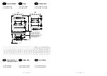
C Schematic diagram
(1) Hot water outlet
(2) Outlet to boiler
(3) Hot water inlet
(4) Cold water inlet
(5) Pump
(6) Safety valve assembly
(7) Thermostat pocket
(8) Electrical connection box
(9) Cover
(10) Fixing brackets
(12) On/off switch
(13) Anode
Operating principles
The cylinder is connected to the
combination boiler in the following manner :
(1) Is connected to the hot water outlets to
be served. (2) Is connected to the cold
water inlet on the boiler. (3) Is connected to
the domestic hot water outlet on the boiler.
(4) Is connected to the incoming cold water
mains supply.
1 – Heating of the stored water
:
The stored is automatically heated by the
combination boiler and is controlled by a
thermostat fitted to the Celectic cylinder.
On demand this thermostat energises the
pump which then circulates the stored
through the secondary heat exchanger of
the combination boiler until the desired
temperature is obtained.
2 – Using the stored hot water
:
When a hot outlet is opened, cold water
from the mains supply enters the Celectic
system via the secondary heat exchanger
in the combination boiler, thus being pre-
heated before it is allowed to mix with the
stored hot water.
B
II serbatoio « CELECTIC » è un sistema
di produzione di un accumulo di acqua
calda da abbinare dalle caldaie miste
Chaffoteaux et Maury.
Lo scaldabagno é munito di una pompa, di
una scatola elettrica di collegamento, di
un gruppo di sicurezza e di un coperchio
di protezione.
II contenitore a fondi positivi è in acciaio
smaltato di grande spessore. Esso è
dotato di un anodo in magnesio operante
come protezione elettrolitica.
L’isolamento termico è assicurato da uno
strato di schiuma poliuretana.
C Schema di principio
(1) Mandata ACS verso prelievo
(2) Mandata verso caldaia
(3) Ritorno ACS caldaia
(4) Ingresso acqua fredda
(5) Pompa
(6) Valvola
(7) Termostato
(8) Scatola di collegamento elettrico
(9) Cuffia di protezione
(10) Staffe d’aggancio
(12) Interruttore
(13) Anodo
Principio di funzionamento
II serbatoio è collegato al circuito sanitaria
caldaia tramite le uscite (2) e (3),
all’impianto ACS tramite l’uscita (1) e
all’arrivo d’acqua fredda tramite l’entrata
(4).
1 – Statica
:
L’acqua del serbatoio viene riscaldata
automaticamente dalla caldaia su
commando del termostato (7) che inserisce
la pompa (5).
Questa ha il compito di far circolare
l’acqua del serbatoio nella caldaia e
provocare il riscaldemento di quest’ultima
alla temperature di regolazione del
termostato.
2 – Dinamica
:
In fase de pralievo, l’acqua fredda che
arriva da (4), passa attraverso lo
scambiatore della calddia, viene in questo
modo riscaldota, prima di entrare nel
serbatoio.
B
De waterverwarmer « CELECTIC » is een
systeem van geaccumuleerde warmwa-
terproduktie, werkend op een mixte
wandketel Chaffoteaux et Maury.
De boiler is uitgerust met een pomp, met
een elektrische doos, een
veiligheidsgroep en een beschermkap.
De kuip met “positieve bodem” is in
geëmailleerd staal van een grote dikte. Zij
is uitgerust met een magnesiumanode
werkend als elektrolyse bescherming.
De warmte wordt behouden door een
polyurethaanmousselaag.
C Werkingsschema
(1) Aankomst sanitair koud water
(2) Vertrek naar de wandketel
(3) Retour sanitair warm water ketel
(4) Vertrek sanitair warm water naar
aftappunt
(5) Pomp
(6) Veiligheidsgroep
(7) Thermostaat
(8) Elektrische aansluitdoos
(9) Beschermkap
(10) Beugels
(12) Schakelaar
(13) Anode
Werkingsprincipe
De boiler wordt aangesloten op het
sanitaire gedeelte van de ketel door de
uitgangen (2) en (3), aan de installatie
SWW door de uitgang (1) en aan de
aankomst van het koud water door de
ingang (4).
1 – Statisch :
Het water van de boiler wordt automatisch
opgewarmd door de ketel op bevel van de
thermostaat (7), welke de werking van de
pomp (5) op gang brengt.
Deze heeft de taak om het water van de
boiler te doen circuleren in de ketel en
veroorzaakt zo de opwarming van deze tot
de ingestelde temperatuur van de
thermostaat.
2 – Dynamisch :
Bij aftapping komt het aankomende koud
water door (4) automatisch door de ketel,
welke op temperatuur gebracht wordt in
de boiler.
________
16
________
SP
D
F
Réglages
L’aquatast du ballon est réglé de façon à
obtenir de l’eau chaude sanitaire à 65° C
environ.
Ainsi, sur les chaudières équipées d’une
consigne ECS de 60° C, il est nécessaire
de régler la température de l’eau chaude
sanitaire au maximum, de façon à ce
qu’elle soit supérieure au point de
consigne du thermostat du ballon.
Montage du capot
Une fois l’ensemble monté, placer le capot
de protection en le glissant sous les deux
pattes à l’arrière du ballon et le fixer par
les deux vis sur la virole du ballon.
Entretien – utilisation
Groupe de sécurité
Afin de s’assurer du bon fonctionnement
du groupe de sécurité, il est nécessaire de
faire fonctionner celui-ci au minimum une
fois par mois en actionnant le levier et en
vérifiant que l’eau s’écoule normalement.
Si l’eau ne s’écoule pas, il y a lieu de faire
venir d’urgence un professionnel, après
avoir arrêté l’appareil.
Anode
Il est obligatoire de changer l’anode tous
les deux ans.
Arrêt de l’installation
IMPORTANT : En cas d’arrêt de la
chaudière il est nécessaire de couper
l’alimentation électrique du ballon. Dans le
cas contraire, la pompe ferait inutilement
circuler de l’eau froide dans la chaudière
de façon permanente.
Chauffage sans eau chaude sanitaire
Si on désire avoir du chauffage sans
provoquer le réchauffage du ballon, il suffit
de mettre en route la chaudière en
laissant l’interrupteur du ballon en position
arrêt.
Chauffage et/ou eau chaude sanitaire
Afin d’obtenir de l’eau chaude sanitaitre,
une fois la chaudière en fonctionnement, il
suffit de manœuvrer l’interrupteur du
ballon ce qui provoque le réchauffement
de l’eau contenue dans celui-ci.
NOTA
:
Etant donné la priorité au
sanitaire de la chaudière celle-ci ne
produira du chauffage que lorsque le
ballon aura été réchauffé.
En cas de non utilisation de l’installation
en période froide, il est nécessaire de
vidanger le ballon pour prévenir le gel.
Fermer l’arrivée d’eau du groupe de
sécurité.
Ouvrir le robinet d’eau chaude.
Démonter le raccordement (rep. B) au
ballon.
Placer un raccord type raccord de tuyau
d’arrosage avec un tube caoutchouc.
Vidanger le ballon par siphonnage.
Remonter le raccordement (Rep. B).
Einstellen
Der Boileraquastat ist für Warmwasser bei
65° geregelt.
So ist es bei Heizkessein mit einer
Einstelltemperatur von 60°C Warmwasser
notwendig, die Temperatur des warmen
Leitungswassers auf die maximale
Leistung einzustellen, damit sie höher als
die Einsteltemperatur des
Boilerthermostates ist.
Montage des Gehäuses
Nach der Gesamtmontage das Schutz-
gehäuse unter die beiden
Hinterhalterungen schieben und mit zwei
Schrauben auf dem Kesselring
festschrauben
Wartung – Benutzung
Sicherheitsanlage
Um das perfekte Funktionieren der
Sicherheitsanlage zu prüfen, diese
min-
destens ein mal im Monat kontrollieren ;
den Hebel in Gang setzen und prüfen daß
das Wasser normal abläuft.
Wenn das Wasser nicht ausfließt, den
Apparat abstellen und sofort den
Wartungsdienst rufen.
Anode
Die anode muß jedes Zweite Jahr
geweehselt werden.
Heizen ohne warmwasserproduktion
wames leitungswasser
.
Will man die Heizung anstellen ohne den
Boiler aufzuheizen, genügt es den Kessel
einzustellen indem der boilerschalter auf
“Stop“ steht.
Heizung und/oder wames leitungswasser
Will man warmes Wasser haben während
der Kessel funktioniert, genügt es den
Boilerschalter einzustellen.
Bemerkung
: Da die Priorität beim
Sanitärwert des Kessels liegt, wird dieser
erst heizen, wenn das Wasser im Boiler
warm ist.
Wird die Anlage bei kalter Temperatur
nicht gebraucht, muß der Boiler geleert
werden, um ein einfrieren zu verhindern.
Die Wasserhahn aufdrehen.
Den fitting (Resp. B) zum boiler
abmontieren.
Ein Verbindungsstück (z. B.
gartenanschluß) mit Schlauch anbringen
und den boiler damit leeren.
Den fitting (Resp. B) wieder aufmontieren.
Reglajes
El acuastato del acumulador esta
regulado de forma qua se pueda obtener
agua caliente sanitaria a 65° C
aproximadamente.
En las calderas equipadas con una
temperatura del agua caliente sanitaria a
60°C, es necesario ajustar la temperatura
del agua caliente sanitaria al máximo,
para que sea superior al punto de
consigna del termostato del acumulador.
Montaje de la tapa
Una vez montado el conjunto, colocar la
tapa de proteccián deslizándola dende las
dos patas situadas detrás del acumulador
y fijarlo mediante los dos tornillos sobre la
carcasa del acumulador.
Mantenimiento – uso
Grupo de seguridad
Con el fin de asegurar un buen
funcionamiento del grupo de seguridad,
es necesario hacerlo funcionar como
mínimo una vez al mes, accionando la
palanca y verificando que el agua corre
normalmente. Si el agua no circula, avisar
urgentemente al S.A.T., una vez parado el
aparato.
Anodo
Es obligatorio cambiar el ánodo cada dos
años.
Paro de la instalación
IMPORTANTE : En caso de paro de la
caldera, es necesario cortar la
alimentación electrica del acumulador. En
caso contrario, la bomba haría circular
inutilmente el agua fría por la caldera
permanentemente.
Calefacción sin agua caliente sanitaria
.
Si deseamos tener calefacción sin
provocar el recalentamiento del
acumulador, basta con poner en marcha
la caldera dejando el interruptor del
accumulador en posición paro.
Calefacción Y/O agua caliente sanitaria
Con el fin de obtener agua caliente
sanitaria, con la caldera funcionando en
calefacción, basta con maniobar el
interruptor del acumulador, lo cual
provoca el recalenta-miento del agua que
éste contiene.
NOTA
: Dada la proridad del agua
caliente sanitaria de la caldera, ésta no
proporcionará calefaccion hasta que el
acumulador no esté recalentado.
En caso de no utilizar la instalación en
temporada de frío, es necesario vaciar el
acumulador para prevenir las heladas.
Cerrar la llegada de agua del grupo de
seguridad.
Abrir un grifo de agua caliente
Desmontar el empalme (loc. B) del acu-
mulador.
Colocar un racor tipo racor de tubo de
grifo de riego con un tubo de cauchouc.
________
5
________
NL
I
GB
DESCRIPTION
DESCRIZIONE
VOORSTELLING
B
The CELECTIC is a hot water system for
use in conjunction with Chaffoteaux et
Maury combination boilers.
The Celectic comes complete with a pump,
and electrical connection box, a safety
valve assembly and protective cover.
The efficient design of the Celectic is
further enhanced by its robust
construction of enamelled steel together
with its polyurethane foam insulation
which ensures minimal heat losses.
A sacrificial magnesium anode is fitted to
the cylinder to give added protection
against any electrolytic action that may
occur.
C Schematic diagram
(1) Hot water outlet
(2) Outlet to boiler
(3) Hot water inlet
(4) Cold water inlet
(5) Pump
(6) Safety valve assembly
(7) Thermostat pocket
(8) Electrical connection box
(9) Cover
(10) Fixing brackets
(12) On/off switch
(13) Anode
Operating principles
The cylinder is connected to the
combination boiler in the following manner :
(1) Is connected to the hot water outlets to
be served. (2) Is connected to the cold
water inlet on the boiler. (3) Is connected to
the domestic hot water outlet on the boiler.
(4) Is connected to the incoming cold water
mains supply.
1 – Heating of the stored water
:
The stored is automatically heated by the
combination boiler and is controlled by a
thermostat fitted to the Celectic cylinder.
On demand this thermostat energises the
pump which then circulates the stored
through the secondary heat exchanger of
the combination boiler until the desired
temperature is obtained.
2 – Using the stored hot water
:
When a hot outlet is opened, cold water
from the mains supply enters the Celectic
system via the secondary heat exchanger
in the combination boiler, thus being pre-
heated before it is allowed to mix with the
stored hot water.
B
II serbatoio « CELECTIC » è un sistema
di produzione di un accumulo di acqua
calda da abbinare dalle caldaie miste
Chaffoteaux et Maury.
Lo scaldabagno é munito di una pompa, di
una scatola elettrica di collegamento, di
un gruppo di sicurezza e di un coperchio
di protezione.
II contenitore a fondi positivi è in acciaio
smaltato di grande spessore. Esso è
dotato di un anodo in magnesio operante
come protezione elettrolitica.
L’isolamento termico è assicurato da uno
strato di schiuma poliuretana.
C Schema di principio
(1) Mandata ACS verso prelievo
(2) Mandata verso caldaia
(3) Ritorno ACS caldaia
(4) Ingresso acqua fredda
(5) Pompa
(6) Valvola
(7) Termostato
(8) Scatola di collegamento elettrico
(9) Cuffia di protezione
(10) Staffe d’aggancio
(12) Interruttore
(13) Anodo
Principio di funzionamento
II serbatoio è collegato al circuito sanitaria
caldaia tramite le uscite (2) e (3),
all’impianto ACS tramite l’uscita (1) e
all’arrivo d’acqua fredda tramite l’entrata
(4).
1 – Statica
:
L’acqua del serbatoio viene riscaldata
automaticamente dalla caldaia su
commando del termostato (7) che inserisce
la pompa (5).
Questa ha il compito di far circolare
l’acqua del serbatoio nella caldaia e
provocare il riscaldemento di quest’ultima
alla temperature di regolazione del
termostato.
2 – Dinamica
:
In fase de pralievo, l’acqua fredda che
arriva da (4), passa attraverso lo
scambiatore della calddia, viene in questo
modo riscaldota, prima di entrare nel
serbatoio.
B
De waterverwarmer « CELECTIC » is een
systeem van geaccumuleerde warmwa-
terproduktie, werkend op een mixte
wandketel Chaffoteaux et Maury.
De boiler is uitgerust met een pomp, met
een elektrische doos, een
veiligheidsgroep en een beschermkap.
De kuip met “positieve bodem” is in
geëmailleerd staal van een grote dikte. Zij
is uitgerust met een magnesiumanode
werkend als elektrolyse bescherming.
De warmte wordt behouden door een
polyurethaanmousselaag.
C Werkingsschema
(1) Aankomst sanitair koud water
(2) Vertrek naar de wandketel
(3) Retour sanitair warm water ketel
(4) Vertrek sanitair warm water naar
aftappunt
(5) Pomp
(6) Veiligheidsgroep
(7) Thermostaat
(8) Elektrische aansluitdoos
(9) Beschermkap
(10) Beugels
(12) Schakelaar
(13) Anode
Werkingsprincipe
De boiler wordt aangesloten op het
sanitaire gedeelte van de ketel door de
uitgangen (2) en (3), aan de installatie
SWW door de uitgang (1) en aan de
aankomst van het koud water door de
ingang (4).
1 – Statisch :
Het water van de boiler wordt automatisch
opgewarmd door de ketel op bevel van de
thermostaat (7), welke de werking van de
pomp (5) op gang brengt.
Deze heeft de taak om het water van de
boiler te doen circuleren in de ketel en
veroorzaakt zo de opwarming van deze tot
de ingestelde temperatuur van de
thermostaat.
2 – Dynamisch :
Bij aftapping komt het aankomende koud
water door (4) automatisch door de ketel,
welke op temperatuur gebracht wordt in
de boiler.


