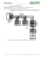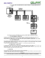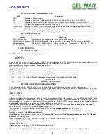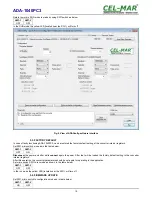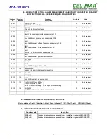
Table register of inverter's status
Bit High byte of State Inverter
Bit Low byte of State Inverter
0
Insulation fault
0 - NO
1 - YES
0
Panel voltage Usol - High
0 - NO
1 - YES
1
Reserved (0)
1
Panel voltage - Low
0 - NO
1 - YES
2
Shutdown by any hardware failure
0 - NO
1 - YES
2
No network / Shutdown by any network error (ENS)
0 - NO
1 - YES
3
Reserved (0)
3
Network voltage Uac - High
0 - NO
1 - YES
4
Reserved (0)
4
Network voltage Uac - Low
0 - NO
1 - YES
5
Reserved (0)
5
Network frequency Fac - High
0 - NO
1 - YES
6
Inverter off remotely
0 - NO
1 - YES
6
Network frequency Fac - Low
0 - NO
1 - YES
7
Inverter on
0 - NO
1 - YES
7
Inverter temperature - High
0 - NO
1 - YES
9. RS232 INTERFACE – PIN DESCRIPTION OF DSUB-9F-DCE SOCKET
Pin
Signal
Description
ADA-1040PC3
1 (DCD)
Level of receiver signal
Connected with DSR
2 (TxD)
Data transmission from ADA-1040PC3
Transmitter
3 (RxD)
Data receiving via ADA-1040PC3
Receiver
4 (DSR)
Readiness of data receiving/ transmission
Connected with DTR
5 (SG)
Signal ground
GND
6 (DTR)
Readiness of data receiving/ transmission
Connected with DSR
7 (CTS)
Device confirms receiving RTS signal from ADA-1040PC3
Connected with RTS
8 (RTS)
Device reports readiness to receive data
Connected with CTS
9 (RI)
Call rate
Not connected
21
ADA-1040PC3
Содержание ADA-1040PC3
Страница 23: ...23 ADA 1040PC3...

